Francis Rouessac - Chemical Analysis
Здесь есть возможность читать онлайн «Francis Rouessac - Chemical Analysis» — ознакомительный отрывок электронной книги совершенно бесплатно, а после прочтения отрывка купить полную версию. В некоторых случаях можно слушать аудио, скачать через торрент в формате fb2 и присутствует краткое содержание. Жанр: unrecognised, на английском языке. Описание произведения, (предисловие) а так же отзывы посетителей доступны на портале библиотеки ЛибКат.
- Название:Chemical Analysis
- Автор:
- Жанр:
- Год:неизвестен
- ISBN:нет данных
- Рейтинг книги:3 / 5. Голосов: 1
-
Избранное:Добавить в избранное
- Отзывы:
-
Ваша оценка:
Chemical Analysis: краткое содержание, описание и аннотация
Предлагаем к чтению аннотацию, описание, краткое содержание или предисловие (зависит от того, что написал сам автор книги «Chemical Analysis»). Если вы не нашли необходимую информацию о книге — напишите в комментариях, мы постараемся отыскать её.
provides an up-to-date overview of the common methods used for qualitative, quantitative, and structural chemical analysis. Assuming no background knowledge in the subject, this student-friendly textbook covers the fundamental principles and practical aspects of more than 20 separation and spectroscopic methods, as well as other important techniques such as elemental analysis, electrochemistry and isotopic labelling methods.
Avoiding technical complexity and theoretical depth, clear and accessible chapters explain the basic concepts of each method and its corresponding instrumental techniques—supported by explanatory diagrams, illustrations, and photographs of commercial instruments. The new edition includes revised coverage of recent developments in supercritical fluid chromatography, capillary electrophoresis, miniaturized sensors, automatic analyzers, digitization and computing power, and more. Offering a well-balanced introduction to a wide range of analytical and instrumentation techniques, this textbook:
Provides a detailed overview of analysis methods used in the chemical and agri-food industries, medical analysis laboratories, and environmental sciences Covers various separation methods including chromatography, electrophoresis and electrochromatography Describes UV and infrared spectroscopy, fluorimetry and chemiluminescence, x-ray fluorescence, nuclear magnetic resonance and other common spectrometric methods such atomic or flame emission, atomic absorption and mass spectrometry Includes concise overview chapters on the general aspects of chromatography, sample preparation strategies, and basic statistical parameters Features examples, end-of-chapter problems with solutions, and a companion website featuring PowerPoint slides for instructors
, is the perfect textbook for undergraduates taking introductory courses in instrumental analytical chemistry, students in chemistry, pharmacy, biochemistry, and environmental science programs looking for information on the techniques and instruments available, and industry technicians working with problems of chemical analysis.
Review of Second Edition “An essential introduction to a wide range of analytical and instrumentation techniques that have been developed and improved in recent years.”
–
Chemical Analysis — читать онлайн ознакомительный отрывок
Ниже представлен текст книги, разбитый по страницам. Система сохранения места последней прочитанной страницы, позволяет с удобством читать онлайн бесплатно книгу «Chemical Analysis», без необходимости каждый раз заново искать на чём Вы остановились. Поставьте закладку, и сможете в любой момент перейти на страницу, на которой закончили чтение.
Интервал:
Закладка:
Elimination of the solvent or low‐boiling point compounds.
Larger injection volume.
The three principal modes of operation are named split cold injection, splitless cold injection and injection with elimination of solvent.
Split cold injection : the sample is introduced into the cold vaporization chamber. The vent valve is then immediately opened and the injector is heated. As the sample is not instantaneously vaporized, the solvent and the different compounds penetrate the column in the order of their boiling points. In this way, the column is never overloaded.
Splitless cold injection : this mode is employed for trace analysis. The vent valve is closed during injection. The injection chamber is then heated in order to transfer the sample into the column, which is maintained cold.
Injection with elimination of solvent : the sample is introduced into the cold injector, after which the vent valve is opened. The vent flow rate is very high and can reach 1,000 ml/min in order to eliminate all of the solvent. The injector is then heated to permit transfer of the less volatile compounds onto the column, with the vent valve now being closed ( splitless mode). In this way, it is possible to inject up to 50 μl in a single injection or up to 500 μl of sample solution in a volatile solvent, over several injections. This method eliminates the preliminary concentration step of the sample prior to injection.
Injection after pyrolysis. Solid samples that are not soluble in solvents may nevertheless be the subject of a GC analysis by placing a device upstream from the injector. This device brings the sample to 600°C to decompose it into smaller molecules. The composition of these molecules will be used to identify the starting sample. The related injector is generally of the PTV type. This method is used for polymers, paints, rubber, additives or textiles.
2.4 TEMPERATURE‐CONTROLLED OVEN
The gas chromatograph comprises a temperature‐controlled enclosure, or ventilated oven, in which the column is placed. This column can be heated uniformly to more than 400°C, if necessary. The enclosure must have low thermal inertia, enabling a rapid but controlled temperature rise when a temperature gradient is included in the analysis (gradient can reach 130–140°C / min. with excellent stabilization at 0.05°C). By installation of a cryogenic valve fed with nitrogen or carbon dioxide in the liquid state, the oven can be very quickly regulated at low temperature. This valve is essential when we work with an autosampler and a temperature gradient, as temperature cycles must succeed each other at a few minutes’ interval between two injections.
2.5 COLUMNS
There are two column types, which differ in their performance: packed columns, which are being progressively abandoned, and capillary , or open tube , columns, which have a very small diameter ( Figure 2.7). Their performance levels are different. For packed columns, the stationary phase is deposited by impregnation or by covalent bonds between the stationary phase and the porous support. For capillary columns, a thin layer of stationary phase is deposited onto, or grafted to, the inner surface of the column.
2.5.1 Packed Columns
These columns, less commonly used today, have diameters of 1/8 or 1/4 inch (3.18 or 6.35 mm) and a length of 1–3 m. Manufactured from steel, the internal wall of the tube is treated to avoid catalytic effects with the sample. The carrier gas flow rate ranges from 10 to 40 ml/min.
In gas–liquid chromatography, the column contains an inert porous support onto which the stationary phase can be impregnated or grafted (between 3 and 25%), depending on the expected application.
In gas–solid chromatography, the stationary phase is composed of an adsorbent solid (molecular sieve, glassy carbon or porous polymer).
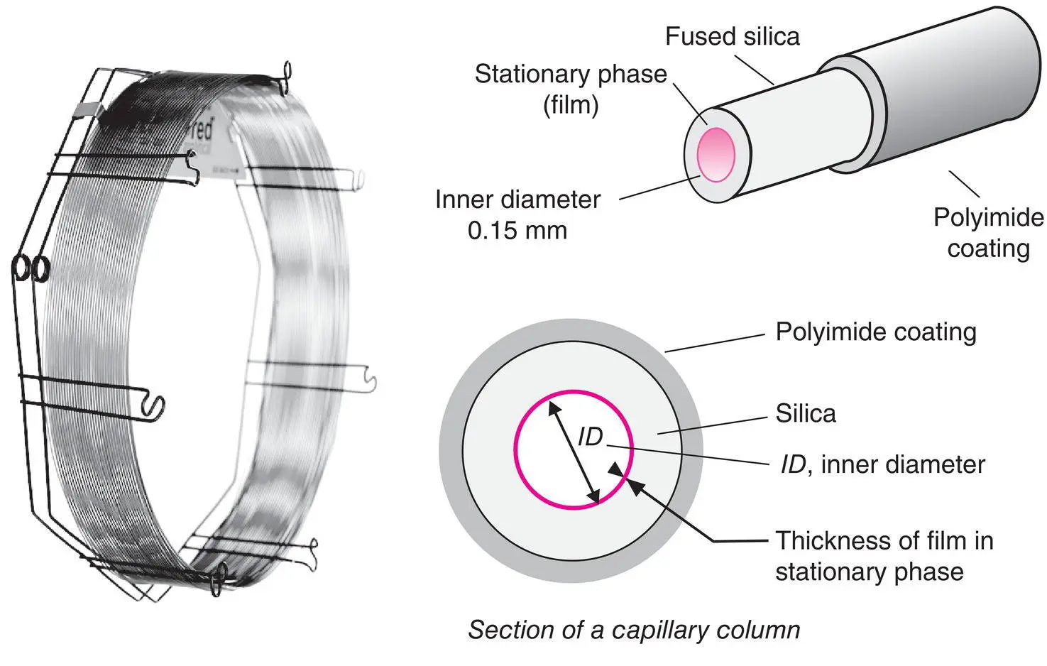
Figure 2.7 Capillary columns. Representation of a 50 m long commercial capillary column coiled around its metal support (Document from the Alltech Associates Inc.) and close‐up of a column. At this scale, the thickness of the stationary phase will scarcely be visible.
While less efficient than capillary columns, owing to preferential paths (Eddy factor of the Van Deemter curve), they are still used for some standardized routine analyses. Nevertheless, these are not adapted to trace analyses, and the progressive generalization of GC‐MS coupling has greatly reduced their use.
Porous supports are made of spherical particles of around 0.2 mm in diameter. These are obtained from fossilized silicates (kieselguhr, tripoli) whose backbone is chemically comparable to that of amorphous silica. One of the most common goes by the name of Chromosorb ®. Their specific surface area is variable (between 2 and 8 m 2 / g).
2.5.2 Capillary Columns (Open Tubular)
They are usually made of the highest purity fused silica obtained by the combustion of tetrachlorosilane (SiCl 4) in an oxygen‐rich atmosphere. The internal diameter of the tube used for these columns varies from 100 to 530 μm. The technology is particularly delicate in order to obtain perfectly cylindrical columns with a thickness of 50 μm and lengths going up to 100 m ( Figure 2.7). These columns have a polyimide outer coating, which is a thermally stable polymer ( T max= 370°C), to make them less fragile, both chemically and mechanically. They can be wound into coils around a lightweight metal circular support. Some manufacturers offer columns made from a metal capillary (aluminium, nickel or steel) which tolerates high operating temperatures on the order of 450°C, providing that the stationary phase is stable enough. The internal surface of the column is usually treated to promote good bonding for the stationary phase. This could be a chemical treatment or the deposit of a thin layer of alumina or silica gel.
The regular thickness of the stationary phase can vary between 0.05 and 5 μm. It is either simply deposited or better yet grafted with covalent bonds, possibly followed by a polymerization with cross‐linking on the wall. This deposit is obtained by evaporating a solution or by polymerization in situ in contact with the wall. These are WCOT ( wall ‐ coated open tubular ) or PLOT ( porous layer open tubular ) columns, depending upon the nature of the stationary phase employed. Columns are particularly stable and can be rinsed periodically with solvents, which enable them to recover their initial performance levels.
To compare or anticipate the behaviour of capillary columns, it is useful to know the phase ratio β = V M / V S. By designating ID as the internal diameter of the column and d fas the thickness of the deposited film, an approximate calculation leads to:
(2.1) 
The column’s capacity is related to the phase ratio but also, for each solute, to its retention time, since k is inversely proportional to it. The phase ratio β , accessible from the physical characteristics of the column, and k (retention factor) from the chromatogram, help us calculate the partition coefficient K of a solute, whose value is generally quite high (1,000 for example) owing to the nature of the mobile phase (gas).
Читать дальшеИнтервал:
Закладка:
Похожие книги на «Chemical Analysis»
Представляем Вашему вниманию похожие книги на «Chemical Analysis» списком для выбора. Мы отобрали схожую по названию и смыслу литературу в надежде предоставить читателям больше вариантов отыскать новые, интересные, ещё непрочитанные произведения.


![Евгений Матерёв - Музеи… или вдохновляющая музыка The Chemical Brothers [litres самиздат]](/books/437288/evgenij-materev-muzei-ili-vdohnovlyayuchaya-muzyka-th-thumb.webp)


Обсуждение, отзывы о книге «Chemical Analysis» и просто собственные мнения читателей. Оставьте ваши комментарии, напишите, что Вы думаете о произведении, его смысле или главных героях. Укажите что конкретно понравилось, а что нет, и почему Вы так считаете.