Joel P. Dunsmore - Handbook of Microwave Component Measurements
Здесь есть возможность читать онлайн «Joel P. Dunsmore - Handbook of Microwave Component Measurements» — ознакомительный отрывок электронной книги совершенно бесплатно, а после прочтения отрывка купить полную версию. В некоторых случаях можно слушать аудио, скачать через торрент в формате fb2 и присутствует краткое содержание. Жанр: unrecognised, на английском языке. Описание произведения, (предисловие) а так же отзывы посетителей доступны на портале библиотеки ЛибКат.

- Название:Handbook of Microwave Component Measurements
- Автор:
- Жанр:
- Год:неизвестен
- ISBN:нет данных
- Рейтинг книги:5 / 5. Голосов: 1
-
Избранное:Добавить в избранное
- Отзывы:
-
Ваша оценка:
Handbook of Microwave Component Measurements: краткое содержание, описание и аннотация
Предлагаем к чтению аннотацию, описание, краткое содержание или предисловие (зависит от того, что написал сам автор книги «Handbook of Microwave Component Measurements»). Если вы не нашли необходимую информацию о книге — напишите в комментариях, мы постараемся отыскать её.
Handbook of Microwave Component Measurements — читать онлайн ознакомительный отрывок
Ниже представлен текст книги, разбитый по страницам. Система сохранения места последней прочитанной страницы, позволяет с удобством читать онлайн бесплатно книгу «Handbook of Microwave Component Measurements», без необходимости каждый раз заново искать на чём Вы остановились. Поставьте закладку, и сможете в любой момент перейти на страницу, на которой закончили чтение.
Интервал:
Закладка:
To accomplish full cross‐bar testing, the configuration of the test set shown in Figure 2.26is used. In the general configuration, sets of 1 × n switch trees are cross connected to 1 × 2 switches at each port. This configuration provides for any path to be measured, but the unused ports are terminated back in the 1 × n switches, which are terminated internally in a load. If the 1 × N switches are not internally terminated (rather, they are left open), then the 1 × 2 switch must provide a termination for an unused port. Figure 2.26shows a full cross‐bar switch constructed of a 1 × 2 port switch connecting to a pair of 1 × n switches. With this configuration, every port that is not connected to the VNA is terminated in a switch load. However, it is difficult to use this type of switch matrix to perform full N‐by‐N calibrations as the exact value of the load termination of any port changes depending upon the switch settings of other ports.
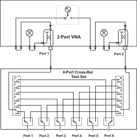
Figure 2.26 Full cross‐bar switching test set.
For example, if test set ports 1 and 6 are the active ports, ports 2–5 are terminated in the 1 × 6 switch on the left. If test set port 5 is made active, then port 6 may be terminated in the 1 × 6 switch on the right. The fact that the termination of the port depends on the path selected makes calibration beyond the two ports selected more difficult.
Custom switching test sets might have a reduced number of paths, forming a combination of full cross‐bar on some ports and simple switch trees on other ports. For high speed and reliability, solid‐state switching is preferred. Mechanical switches have almost no loss, but solid‐state switches can have considerable loss at microwave frequencies. This loss is after the directional‐coupler and dramatically degrades the RF performance of the system. On the other hand, mechanical switches can have slight changes in return loss for each switch cycle, also leading to instabilities. Thus, this architecture of switches after the directional‐couplers of the VNA is a simple one, but at a cost of substantially reduced stability and performance.
2.2.7.2 Extension Test Sets
To satisfy the requirement for making full N‐by‐N calibrated measurements, often referred to as full N‐port cal measurements , a test set design has been developed that includes both directional‐couplers and switches. The original implementation of this style of extension test sets was configured to supply two additional ports to a two‐port VNA to create a 4‐port VNA for making the first balanced and differential measurements. The general idea of an extension test set is to essentially extend the source switch matrix of the VNA to more outputs through a source switch and also extend the internal receivers to more ports through a receiver switch. This requires that an additional test port coupler be provided for each additional port. Because the switching occurs behind the VNA directional‐couplers, they are still available as test ports: the ports on the test set extend the total number of ports available, which is why it's called an extension test set. Figure 2.27shows block diagrams for a simple two‐port extension test set.
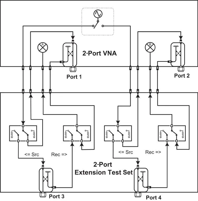
Figure 2.27 Extension test set block diagram.
One key point of the block diagram is that the test set breaks into the source and receiver loops behind the test port coupler. Since any number of switch paths can be supplied behind the test couplers, there is in theory no limit to the number of ports that can be used. Further, this block diagram allows additional test sets to be added so that any number of test ports can be created by stacking extension test sets. Common configurations are 4‐port extension test sets for a 4‐port VNA to extend to a total of 8 ports, 10‐port extension test sets for a 2‐port VNA to achieve a total 12 ports, and 12‐port extension test sets for a 4‐port VNA to achieve a total of 16 ports. Figure 2.28shows a 4‐port VNA with two 4‐port extension test sets to create a 12‐port system.
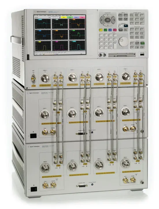
Figure 2.28 12‐port system using a 4‐port VNA and two extension test sets.
Source: Photo courtesy of Keysight Technologies.
The switches may be either mechanical switches or solid‐state switches. Because all the switching occurs behind the test port couplers, the stability and performance of the measurements are much better than that of switching test sets, and loss in the switch, while it reduces the dynamic range, has no effect on stability of the measurements.
In some cases, an option may be provided to add a low‐noise amplifier (LNA) between the coupled port of the test coupler and the switch input. This improves performance as the gain of the LNA improves the dynamic range. Adding amplifiers in between the coupled arm and the switch also removes another source of error. In some cases, the source‐match of a port changes when the source and test port share the same VNA receiver, for example ports 1 and 3 in Figure 2.27. This error is typically small as the difference between the match of the VNA receiver and the match of the switch is small (on the order of −10 dB) and is further reduced by twice the coupling loss (32 dB) resulting in a typical source‐match error smaller than −40 dB. In most cases it has a negligible effect, but in some measurements, particularly circulators or couplers, it can become significant and is not removed in calibration, so adding an amplifier ensures that the match presented to the coupled arm is constant. The test ports also change load characteristics depending upon if they are terminated in a switch or the VNA internal load; however, the N‐port calibration methods characterize both these states and fully correct for the difference.
2.2.7.3 True‐Multiport VNAs
While the extension test set provides a directional‐coupler on each port of the test system, the reference coupler and the measurement receivers are shared, so the number of ports that can be measured simultaneously is limited to the number of receivers in the base instrument. Recently, improved integration has made it possible to include a full VNA test receiver on each port, so true‐multiport VNAs are now available. These come in a variety of form factors, but for the most part they are intended for manufacturing operations, where size and footprint are important.
One of the first offerings for a large‐port‐count true‐multiport VNA was the ZNBT from Rohde & Schwarz. It provides options from 8 to 24 ports, with a faceless instrument. In this configuration, it had six independent sources (one for each four ports) as well as receivers on each port.
A modular form of multiport VNAs has been introduced in a PXI format, which allows for configuring from 2 to more than 68 ports, potentially up to 100 ports, depending upon the number and model of VNA modules used. Figure 2.29shows a modular system with eight 6‐port modules (Keysight model M9804‐006) and one 2‐port module (Keysight model M9804‐002), configured as a 50‐port VNA system. There is one source per module, but a full dual‐reflectometer and dual RF receiver for each port. Thus, the 2‐port modules have 1 source and 4 receivers; the 4‐port modules have 1 source and 8 receivers, and the 6‐port modules have 1 source and 12 receivers.
Читать дальшеИнтервал:
Закладка:
Похожие книги на «Handbook of Microwave Component Measurements»
Представляем Вашему вниманию похожие книги на «Handbook of Microwave Component Measurements» списком для выбора. Мы отобрали схожую по названию и смыслу литературу в надежде предоставить читателям больше вариантов отыскать новые, интересные, ещё непрочитанные произведения.


Обсуждение, отзывы о книге «Handbook of Microwave Component Measurements» и просто собственные мнения читателей. Оставьте ваши комментарии, напишите, что Вы думаете о произведении, его смысле или главных героях. Укажите что конкретно понравилось, а что нет, и почему Вы так считаете.