Joel P. Dunsmore - Handbook of Microwave Component Measurements
Здесь есть возможность читать онлайн «Joel P. Dunsmore - Handbook of Microwave Component Measurements» — ознакомительный отрывок электронной книги совершенно бесплатно, а после прочтения отрывка купить полную версию. В некоторых случаях можно слушать аудио, скачать через торрент в формате fb2 и присутствует краткое содержание. Жанр: unrecognised, на английском языке. Описание произведения, (предисловие) а так же отзывы посетителей доступны на портале библиотеки ЛибКат.

- Название:Handbook of Microwave Component Measurements
- Автор:
- Жанр:
- Год:неизвестен
- ISBN:нет данных
- Рейтинг книги:5 / 5. Голосов: 1
-
Избранное:Добавить в избранное
- Отзывы:
-
Ваша оценка:
Handbook of Microwave Component Measurements: краткое содержание, описание и аннотация
Предлагаем к чтению аннотацию, описание, краткое содержание или предисловие (зависит от того, что написал сам автор книги «Handbook of Microwave Component Measurements»). Если вы не нашли необходимую информацию о книге — напишите в комментариях, мы постараемся отыскать её.
Handbook of Microwave Component Measurements — читать онлайн ознакомительный отрывок
Ниже представлен текст книги, разбитый по страницам. Система сохранения места последней прочитанной страницы, позволяет с удобством читать онлайн бесплатно книгу «Handbook of Microwave Component Measurements», без необходимости каждый раз заново искать на чём Вы остановились. Поставьте закладку, и сможете в любой момент перейти на страницу, на которой закончили чтение.
Интервал:
Закладка:
From this modification, the RF implementation of the bridge can be better understood. Since the low side of the detector is now ground, the resistor represented by Rdet and R4 can be replaced with transmission line structures of similar impedances, representing the RF ports of the directional bridge, as shown in Figure 2.14. In this figure, the Rdet resistor is replaced with the coupled port of the bridge, and one can see that the RF energy flowing from the source appears equally at both the center conductor and the ground of isolated port.
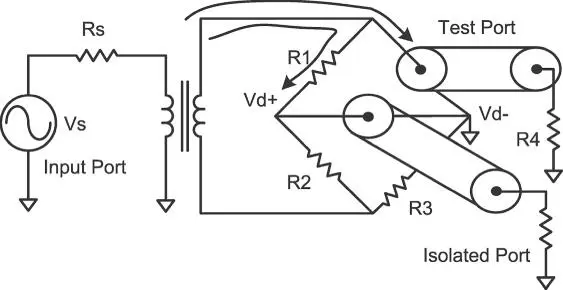
Figure 2.14 Replacing bridge elements with RF ports.
However, since the RF current appears at the test port, relative to ground, a portion of the RF signal will appear across R4; the relative value of the voltage on R4 to Vs/2 is the insertion loss of the directional bridge. If the bridge uses equal resistors, then R1, R2, R3, and R4 as well as Rs are all 50 Ω. With these values, it is easy to see that Vs is applied equally to R1 and R2, as well as R3 and R4, so that the voltage across R4 is one‐fourth the source voltage. Therefore, the loss of an equal resistor balanced bridge is one‐half voltage applied at the bridge input, or −6 dB. In general, the insertion loss of a bridge, where R S= R 4= Z 0is
(2.4) 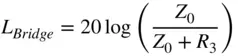
From this description we can see that in the case where the bridge is terminated in Z 0, there is no signal in the isolated port, demonstrating that this bridge isolates the incident signal. The first criteria of a directional device is satisfied. The second criteria is that the bridge does respond to the reflection signal from the test port. To understand how that occurs, it is useful to redraw the bridge, bringing the ground point of the test port down to the bottom of a redrawn circuit, as shown in Figure 2.15.

Figure 2.15 A bridge redrawn to show the coupling factor.
In this drawing, the source has been moved from the input to the output, but the bridge circuit is topologically identical to the previous figure. When driven from the test port (or when measuring a reflected signal), the isolated arm becomes the coupled arm, and the coupling factor of the coupled arm can be computed as
(2.5) 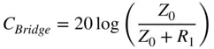
For the case of an equal resistor bridge, the coupling factor is equal to the loss, −6 dB. If R1 is not equal to Z 0, R3 can be computed as
(2.6) 
Note that the loss is directly proportional to the coupling as
(2.7) 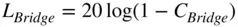
For RF VNAs, it is common to use a directional bridge in the test set. Directional bridges of this type have been used since the 1970s, and an example of such a bridge used in the HP 8753B is shown in Figure 2.16. This bridge has been modified to have an unequal coupling and loss, so the insertion loss is lower than normal (around −1.5 dB), and the coupling is higher than normal (around −16 dB) for a Wheatstone bridge.
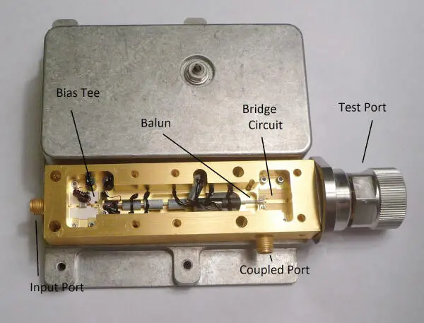
Figure 2.16 An example of a directional bridge from the HP 8753B.
The RF performance of such a microwave bridge is shown in Figure 2.17. The insertion loss increases with frequency due to the loss of the coax balun and increased coupling due to parasitic series inductance in R3. This same inductance causes a degradation of directivity in the bridge as frequency increases. Bridges are inherently lossy structures, where some of the power is absorbed by the resistive elements in the bridge. The power absorbed by the bridge is equal to the insertion loss of the bridge minus the power coupled to the coupled port.

Figure 2.17 RF performance of a directional bridge.
Bridges of this type have been used successfully up to 27 GHz.
2.2.4.2 Directional Couplers
Directional couplers are more often used in higher‐microwave frequency ranges because of the difficulty of maintaining good bridge performance at high frequencies. Directional coupler design is a broad topic, and much literature has been devoted to structures that can be used as couplers. However, for use in VNAs, there are some particular characteristics that are critical. In general, commercial directional‐couplers are designed to maintain a flat coupling factor over their bandwidth, and the bandwidth is limited by this coupling factor. Couplers used for VNA reflectometers require wide bandwidths, so rather than a flat response, they are often designed with an equal‐ripple or Chebyshev response. Ripple in the loss or coupling factor is not much concern in a modern VNA, where calibration techniques can remove almost any frequency response error. Isolation is an important criteria in VNA couplers. One attribute about directional‐couplers that distinguish them from bridges is that they are ideally lossless devices such that all the power applied is either coupled (to the coupled port or the internal load) or transmitted through the coupler. The relationship between insertion loss and coupling factor is
(2.8) 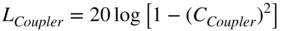
Directional couplers typically come in one of three forms: waveguide couplers, microstrip couplers, and stripline couplers.
Waveguide couplers are most common at mm‐wave frequencies but have the inherent limitation of narrowband operation due to the narrowband nature of waveguides. The structure of waveguide couplers is a 4‐port device with the main arm connected in such a way as to have irises (or holes) to a second waveguide. The second waveguide can have two ports or one port internally terminated. The nature of the coupler is symmetrical. In theory either port can be the coupled port; in practice a load is often embedded in the coupled arm. Because of the fundamental function of a waveguide coupler, the forward coupled wave comes out of the waveguide port nearest the test port. This often causes confusion in the symbols used.
A microstrip or stripline coupler uses a different electric‐magnetic (EM) configuration to perform coupling, and the coupled arm of these couplers is the one farthest from the test port. Microstrip couplers often suffer from the fact that there is some dispersion in microstrip lines, and since the even‐ and odd‐mode waves in the coupled lines experience different effective dielectric constants, they will have different velocities of propagation. This makes it more difficult to create microstrip couplers with good isolation. For this reason, many VNA couplers are in the form of stripline (or slabline, which is similar to stripline but with a rectangular center conductor thickness), suspended in air. These couplers are designed to have very stable coupling and isolation factors. For a VNA, it is not so important what the exact directivity is, as long as it is completely stable. Figure 2.18shows an example of a directional‐coupler used in VNAs. The test port connector is one attribute that differentiates this from a commercially available directional‐coupler that might be used as component in a different system. This connector is designed to be firmly mounted to the VNA front panel and withstand numerous connections and reconnections. This coupler has an integrated load and so exposes only three ports.
Читать дальшеИнтервал:
Закладка:
Похожие книги на «Handbook of Microwave Component Measurements»
Представляем Вашему вниманию похожие книги на «Handbook of Microwave Component Measurements» списком для выбора. Мы отобрали схожую по названию и смыслу литературу в надежде предоставить читателям больше вариантов отыскать новые, интересные, ещё непрочитанные произведения.


Обсуждение, отзывы о книге «Handbook of Microwave Component Measurements» и просто собственные мнения читателей. Оставьте ваши комментарии, напишите, что Вы думаете о произведении, его смысле или главных героях. Укажите что конкретно понравилось, а что нет, и почему Вы так считаете.