Joel P. Dunsmore - Handbook of Microwave Component Measurements
Здесь есть возможность читать онлайн «Joel P. Dunsmore - Handbook of Microwave Component Measurements» — ознакомительный отрывок электронной книги совершенно бесплатно, а после прочтения отрывка купить полную версию. В некоторых случаях можно слушать аудио, скачать через торрент в формате fb2 и присутствует краткое содержание. Жанр: unrecognised, на английском языке. Описание произведения, (предисловие) а так же отзывы посетителей доступны на портале библиотеки ЛибКат.

- Название:Handbook of Microwave Component Measurements
- Автор:
- Жанр:
- Год:неизвестен
- ISBN:нет данных
- Рейтинг книги:5 / 5. Голосов: 1
-
Избранное:Добавить в избранное
- Отзывы:
-
Ваша оценка:
Handbook of Microwave Component Measurements: краткое содержание, описание и аннотация
Предлагаем к чтению аннотацию, описание, краткое содержание или предисловие (зависит от того, что написал сам автор книги «Handbook of Microwave Component Measurements»). Если вы не нашли необходимую информацию о книге — напишите в комментариях, мы постараемся отыскать её.
Handbook of Microwave Component Measurements — читать онлайн ознакомительный отрывок
Ниже представлен текст книги, разбитый по страницам. Система сохранения места последней прочитанной страницы, позволяет с удобством читать онлайн бесплатно книгу «Handbook of Microwave Component Measurements», без необходимости каждый раз заново искать на чём Вы остановились. Поставьте закладку, и сможете в любой момент перейти на страницу, на которой закончили чтение.
Интервал:
Закладка:
2.2.2 Understanding Source‐Match
One of the most confusing issues with respect to VNA measurements is the idea of source‐match. Source‐match also affects non‐VNA measurements when signal sources are connected directly to a DUT, but in such cases it is almost always ignored as its affect cannot be determined; but in VNA measurements, the port 1 reflectometer can help to determine the exact effect of mismatch between the source and the DUT and correct for these errors. In fact, there are three different and distinct source attributes that are often confused as the source‐match of a VNA, and each affects different measurements in different ways.
2.2.2.1 Ratio Source‐Match
The ratio source‐match is that match that will affect the results of a ratio measurement, given a DUT is not perfectly matched to the reference impedance. The value of the ratio source‐match, most commonly called the raw source‐match or uncorrected source‐match , is derived from a combination of the quality of the reference channel signal‐separation device and any mismatch between this device and the input port of the DUT. This is always the value used to compute the uncertainty or accuracy of a gain or return loss measurement. But this match applies only to parameters that have a ratio of some receiver to the reference receiver. In this case the reference receiver is used to measure the change in source drive power incident to the DUT, and the error‐correction math removes the ripple at the output of the DUT associated with the measured incident ripple in power. Thus, for linear measurements such as S21, where the output signal is linearly related to the input signal, the ratio is not affected by changes in incident power to the extent that the reference receiver properly measures the actual incident wave at the DUT.
Errors in the measurement of the actual incident wave are mostly attributed to the ratio source‐match of the VNA. The ratio source‐match can be determined during the calibration process and is shown in Figure 2.5for two cases of reference channel signal separation: the upper trace is using a two‐resistor power splitter, and the lower trace is using a directional‐coupler. While the detailed response is different, the overall quality is quite similar between the two cases.
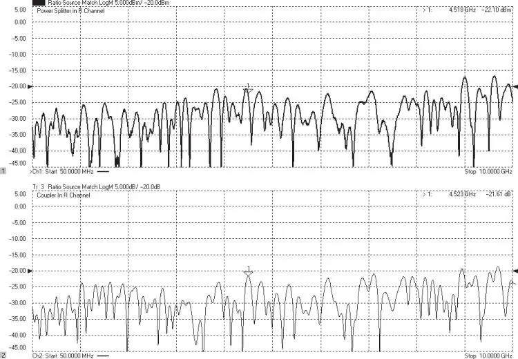
Figure 2.5 Ratio source match: trace when using a power splitter (upper) and trace when using a directional‐coupler (lower).
When a splitter is used, since the splitter uses equal 50 Ω resistors in most cases, the input match to the splitter (as it appears from the source) is nominally 50 Ω, and the loss through the splitter is about 6 dB. The mathematical process of taking the ratio has the effect of creating a virtual ground at the common node of the splitter, so the ratio source‐match is a measure of the quality of the internal 50 Ω resistor.
Interestingly, for the case where the reference comes from a coupler, in the absence of other sources of mismatch after the coupler, the ratio source‐match will be identical to the directivity of the reference coupler. This makes sense as directivity is a measure of the reverse signal leaking into the coupled port, and this signal adds to the reference receiver reading even though it is not part of the incident signal, thus causing an error in ratio measurements.
2.2.2.2 Power Source‐Match
The power source‐match is the value that describes how the output power of the source varies with the applied load. If the power match is zero (perfectly matched), then the output forward wave, a1 , would not be affected at all by the load. If the reference coupler is not ideal (that is, it has some leakage), it is possible have an ideal power source‐match and a non‐ideal ratio source‐match. Conversely, if the reference coupler is perfect but the source has a mismatch, the ratio source‐match may be ideal, but there is a larger power source‐match error. In some ideally constructed S‐parameter measurement architectures, where all components are ideal, the power source‐match is not zero. Consider the block diagram of Figure 2.1simplified in Figure 2.6, where a two‐resistor power splitter is used, and the source impedance is also 50 Ω.
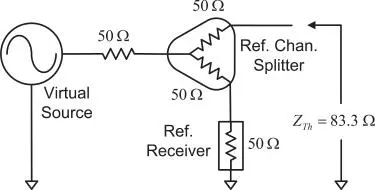
Figure 2.6 Simplified diagram of source power match.
From the test port one sees a series of 50 Ω resistance (of the splitter), behind which is the 50 Ω source impedance in parallel with 100 Ω (50 Ω from the splitter, 50 Ω from the reference receiver, in series), to generate a power match of
(2.1) 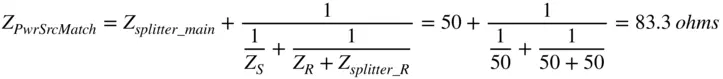
as the Thevenin equivalent impedance. From this it is clear that the for the two‐resistor splitter case, even in an ideal case the power source‐match cannot be Z 0.
In the case where a directional‐coupler is used in the reference channel, the nominal match may be much closer to Z 0. The result of this non‐50 Ω equivalent power source‐match is that when the DUT is not matched, there will be a reflected signal that, while it will be detected by the reference channel and thus compensated for in gain measurements, will cause the a1 wave to vary from the value one sees when the port is terminated in 50 Ω and thus cause error or ripple in the drive power to the DUT, as illustrated in Figure 2.7. The figure shows, in the dark trace, the incident power at a1 for a load at the test port. It is not perfectly flat because of other mismatches in the system after the reference coupler. The light trace shows the result of an open at the test port. This large ripple is because of the poor power source‐match and generates an error in the incident signal of nearly 1 dB. Since this is power measured at the a1 receiver, it is related to the ripple in the output power, but other loss or reflections between the reference splitter and the test port can affect the output power. Other reflections past the reference splitter will add to the power source‐match but are not represented in the a1 measurement. In the case of a linear device, which S‐parameters presume, this is of no consequence; but in the case of non‐linear devices, such as amplifiers in compression, this will directly affect the reported output power. In such a case, the drive power from the VNA can be higher or lower than the displayed power setting, so the amplifier will be further, or lesser, in compression and the power reported will be in error if based on the input drive level.
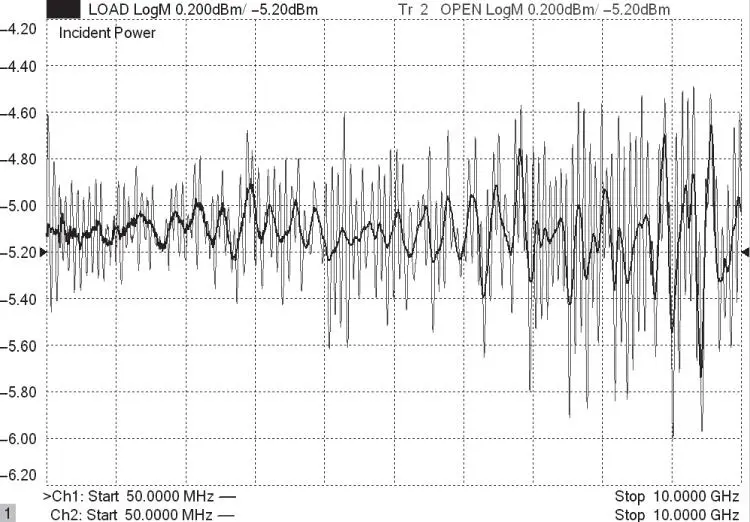
Figure 2.7 Measured incident power into a load termination and an open termination for a VNA with a coupler in the reference channel.
The power source‐match is quite difficult to determine as it is apparent only when there is a mismatch applied at the test port. In essence, one must vary the impedance applied to the test port and measure the change in power coming out of the drive port to infer the power source‐match; it cannot be directly measured. By using a “long‐line” technique, a line‐stretcher, a sliding mismatch, or an impedance tuner as a termination of the test port, and adding a coupler to sample the incident wave (shown in Figure 2.8), one can determine the power source‐match from a series of measurements, where the line stretcher or tuner is changed.
Читать дальшеИнтервал:
Закладка:
Похожие книги на «Handbook of Microwave Component Measurements»
Представляем Вашему вниманию похожие книги на «Handbook of Microwave Component Measurements» списком для выбора. Мы отобрали схожую по названию и смыслу литературу в надежде предоставить читателям больше вариантов отыскать новые, интересные, ещё непрочитанные произведения.


Обсуждение, отзывы о книге «Handbook of Microwave Component Measurements» и просто собственные мнения читателей. Оставьте ваши комментарии, напишите, что Вы думаете о произведении, его смысле или главных героях. Укажите что конкретно понравилось, а что нет, и почему Вы так считаете.