Joel P. Dunsmore - Handbook of Microwave Component Measurements
Здесь есть возможность читать онлайн «Joel P. Dunsmore - Handbook of Microwave Component Measurements» — ознакомительный отрывок электронной книги совершенно бесплатно, а после прочтения отрывка купить полную версию. В некоторых случаях можно слушать аудио, скачать через торрент в формате fb2 и присутствует краткое содержание. Жанр: unrecognised, на английском языке. Описание произведения, (предисловие) а так же отзывы посетителей доступны на портале библиотеки ЛибКат.

- Название:Handbook of Microwave Component Measurements
- Автор:
- Жанр:
- Год:неизвестен
- ISBN:нет данных
- Рейтинг книги:5 / 5. Голосов: 1
-
Избранное:Добавить в избранное
- Отзывы:
-
Ваша оценка:
Handbook of Microwave Component Measurements: краткое содержание, описание и аннотация
Предлагаем к чтению аннотацию, описание, краткое содержание или предисловие (зависит от того, что написал сам автор книги «Handbook of Microwave Component Measurements»). Если вы не нашли необходимую информацию о книге — напишите в комментариях, мы постараемся отыскать её.
Handbook of Microwave Component Measurements — читать онлайн ознакомительный отрывок
Ниже представлен текст книги, разбитый по страницам. Система сохранения места последней прочитанной страницы, позволяет с удобством читать онлайн бесплатно книгу «Handbook of Microwave Component Measurements», без необходимости каждый раз заново искать на чём Вы остановились. Поставьте закладку, и сможете в любой момент перейти на страницу, на которой закончили чтение.
Интервал:
Закладка:
Connectors that are “in series” provide transitions from male to female and provide interconnections between components. These are easiest to characterize as the ports are well defined and typically calibration kits are available and calibration methods are well understood. Connectors that are “between series” are equally well defined, but until recently they have been difficult to characterize as there were not well‐defined standards for between‐series adapters. Recent improvements in calibration algorithms have essentially eliminated any difficulty with characterizing these between‐series adapters. Figure 1.17shows some examples of in‐series and between‐series connectors.
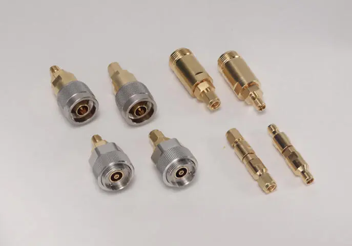
Figure 1.17 In‐series and between‐series connectors.
For microwave work, there are some commonly utilized connector types that are found on the majority of components and equipment. Table 1.1lists these common connectors along with their normal operating frequency range. These are divided into three broad categories: precision sexless connectors, precision male/female connectors, and general‐purpose or utility connectors. These connectors are typically 50 Ω, but a few can be found as 75 Ω versions as well.
Table 1.1 Test connectors used for RF and microwave components
| Name | Outer Conductor Diameter (mm) | Rated Frequency (GHz) | First Mode (GHz) | Maximum Usable Frequency (GHz) |
| Type‐N (50 Ω) precision | 7 | 18 | 18.6 | 26.5 a |
| Type‐N (50 Ω) commercial | 7 | 12 | 12.5 | 15 |
| Type‐N (75 Ω) precision | 7 | 18 | 18.6 | 18 |
| Type‐N (75 Ω) commercial | 7 | 12 | 12.5 | 15 |
| 7 mm | 7 | 18 | 18.6 | 18 |
| SMA | 3.5 | 18 | 19 | 22 |
| 3.5 mm | 3.5 | 26.5 | 28 | 33 |
| 2.92 mm (“K”) | 2.92 | 40 | 44 | 44 |
| 2.4 mm | 2.4 | 50 | 52.5 | 55 |
| 1.85 mm (“V”) | 1.85 | 67 | 68.5 | 70 |
| 1 mm | 1 | 110 | 120 | 130 |
aSome instrument manufacturers place this connector on 26.5 GHz instruments because it is rugged; it has the same first modes as Type‐N and 7 mm.
From Table 1.1one can see that there are three frequencies associated with connectors: the generally understood operating frequency (often dictated by the calibration kit's maximum certified frequency), the frequency of the first mode, and the maximum frequency determined by the waveguide propagating mode of the outer conductor. The operating frequency is always below the first mode and usually by several percent. The first mode in many connectors is due to the support structure for the center pin. It is often made of some plastic material and thus has higher dielectric constant and a lower frequency to support a mode. In connectors and cables, modes is the term used to refer to non‐transverse‐electromagnetic (non‐TEM) propagation that can occur in a circular waveguide mode defined by the inside dimension of the outer conductor. Adding dielectric in the bead that supports the center pin can theoretically lower the mode frequency, but if the bead is short, the mode will be evanescent (non‐propagating) and may not affect the quality of the measurement. At a somewhat higher frequency, there will be a propagating mode in air for the diameter of the center conductor, but if the cable attached to the connector is sufficiently small, this mode may not propagate as well. It is the propagating modes that cause the significant dips in the response, and more importantly, these dips cannot be removed with calibration because they are not localized and because reflections in the mode of transmission far removed for the connector interface can interact with these connector modes, causing the frequency response of the mode effect to change when different devices are connected. If the response of the mode does not change when other devices are connected, it can be calibrated out.
The precision sexless connectors are now found only in metrology labs. Their chief benefit was a repeatable connector that has identical characteristics for each connector. As such, it was easy to create a system calibration, and any part with such connectors could be inserted between two cables in either direction. This was important because in the past it was difficult to deal with “non‐insertable” devices from a calibration sense (a non‐insertable device is one with the same sexed connector on each port, e.g. female‐female). The 7 mm connector is often found on precision attenuators and airlines used as transfer standards. The 7 mm connector is also known as the GPC‐7 for general precision connector, and often as the APC‐7™ for amphenol precision connector. Because these connectors are sexless, there is no need for adapters to provide interconnections between devices or between devices and cables.
1.8.2.1 7 mm Connector (APC‐7, GPC‐7)
The 7 mm connector has a couple of interesting attributes: the center pin has no slots but contains spring‐loaded center collets that protrude slightly from the mating surface, as shown in Figure 1.18.
Figure 1.18 A 7 mm connector.
When mated, the collet from each connector floats against each other, providing a good center contact. There is a slight gap in the slotless outer sleeve of the center pin. As with almost all RF connectors, the outer conductor forms the physical mating plane. On most connectors, there is a slip‐ring‐threaded sleeve surrounded by a coupling nut. To mate, the threaded sleeve is extended on one connector and retracted on the other. On the retracted connector, the coupling nut is extended to engage the other's sleeve and is tightened. Only one coupling nut should be tightened, although it is common but incorrect practice to tighten the other coupling nut. In fact, tightening both coupling nuts can result in the center pins pulling apart and a poorly matched contact. Occasionally, one sees parts that contain only a solid threaded outer conductor (serving the purpose of the threaded sleeve) and no coupling nut. These are more common on older test fixtures intended to mount directly the 7 mm connectors of network analyzer test sets.
1.8.2.2 Type‐N 50 Ω Connector
The Type‐N connector is common in lower‐frequency and higher‐power radio frequency (RF) and microwave work. It has the same outer diameter (7 mm) as the 7 mm connector but is sexed. In fact, this connector has the unusual attribute of having the mating surface for the outer conductor (which is almost always the electrical reference plane) recessed for the female connector. Thus, the female pin protrudes (in an electrical sense) from the reference plane, and the male pin is recessed. Thus, the calibration standards associated with Type‐N connectors have electrical models that are highly asymmetric for male and female standards.
The Type‐N connector has precision forms, including ones with slotless connectors (metrology grade), ones with precision six‐slotted collets and solid outer conductor sleeves (found on most commercial test equipment), and commercial forms with slotted outer conductor sleeves and four or even two slotted female collets. Slotless connectors have a solid hollow cylinder for the female connector with an internal four‐ or six‐finger spring contact that takes up tolerances of the male center pin. As such, the diameter of the female center pin does not depend at all on the radius of the male pin. Typical female contacts with collets expand or contract to accept the male pin, and thus their outer dimension (and thereby their impedance) varies with the diameter tolerance of the male pin.
Читать дальшеИнтервал:
Закладка:
Похожие книги на «Handbook of Microwave Component Measurements»
Представляем Вашему вниманию похожие книги на «Handbook of Microwave Component Measurements» списком для выбора. Мы отобрали схожую по названию и смыслу литературу в надежде предоставить читателям больше вариантов отыскать новые, интересные, ещё непрочитанные произведения.


Обсуждение, отзывы о книге «Handbook of Microwave Component Measurements» и просто собственные мнения читателей. Оставьте ваши комментарии, напишите, что Вы думаете о произведении, его смысле или главных героях. Укажите что конкретно понравилось, а что нет, и почему Вы так считаете.