Joel P. Dunsmore - Handbook of Microwave Component Measurements
Здесь есть возможность читать онлайн «Joel P. Dunsmore - Handbook of Microwave Component Measurements» — ознакомительный отрывок электронной книги совершенно бесплатно, а после прочтения отрывка купить полную версию. В некоторых случаях можно слушать аудио, скачать через торрент в формате fb2 и присутствует краткое содержание. Жанр: unrecognised, на английском языке. Описание произведения, (предисловие) а так же отзывы посетителей доступны на портале библиотеки ЛибКат.

- Название:Handbook of Microwave Component Measurements
- Автор:
- Жанр:
- Год:неизвестен
- ISBN:нет данных
- Рейтинг книги:5 / 5. Голосов: 1
-
Избранное:Добавить в избранное
- Отзывы:
-
Ваша оценка:
Handbook of Microwave Component Measurements: краткое содержание, описание и аннотация
Предлагаем к чтению аннотацию, описание, краткое содержание или предисловие (зависит от того, что написал сам автор книги «Handbook of Microwave Component Measurements»). Если вы не нашли необходимую информацию о книге — напишите в комментариях, мы постараемся отыскать её.
Handbook of Microwave Component Measurements — читать онлайн ознакомительный отрывок
Ниже представлен текст книги, разбитый по страницам. Система сохранения места последней прочитанной страницы, позволяет с удобством читать онлайн бесплатно книгу «Handbook of Microwave Component Measurements», без необходимости каждый раз заново искать на чём Вы остановились. Поставьте закладку, и сможете в любой момент перейти на страницу, на которой закончили чтение.
Интервал:
Закладка:
EVM is affected primarily by distortion of the channel (usually in the transmitter amplifier), nonuniform frequency response (ripples or roll‐off in the channel components), and noise in the system. For a transmitter component, which is the principal contributor to EVM, the noise contribution is generally not significant. In many modulation schemes, such as orthogonal frequency domain multiplexing (OFTM), the signal is broken into many narrow channels, such that the frequency response changes are small over each channel, and thus frequency flatness errors don't contribute to the EVM in these modulation schemes. In other cases, the measurement receiver has the ability to apply frequency response compensation, a kind‐of inverse filtering, to remove the effects of the nonideal frequency response. This is sometimes called equalization , and the EVM measurement is called equa lized EVM . After equalization, the frequency response does not contribute significant errors to the EVM signal.
This leaves only distortion as the predominant contribution to EVM, and as such EVM has become a common figure of merit for distortion in these systems. EVM measurements generally require a full demodulation to evaluate the signal quality, and at this time such capabilities are not generally available in VNAs, but this is likely to change as EVM becomes a significant figure of merit in more systems.
Recently, several papers have been presented (Sombrin 2011; Freiberger et al. 2017) that demonstrate a corresponding relationship between EVM and NPR. These works are compelling and lead one to infer that with further development, the time is near when EVM can be determined without the need for full demodulation, as illustrated in Chapter 8.
1.7 Characteristics of Microwave Components
Microwave components differ from other electrical devices in a few respects. The principal discerning attribute is the fact that the components' size cannot be ignored. In fact, the size of many components is a significant portion of a wavelength at the frequency of interest. This size causes the phase of the signals incident on the device to vary across the device, implying that microwave devices must be treated as distributed devices. A second, related attribute is that the reference ground for the device is not defined by a point but is distributed as well. Indeed, in many cases the ground is not well defined. In some situations, grounds for a device are isolated by sufficient distance that signal propagation can occur from one device ground to another. Further, even if devices are defined as series only (with no ground contact), one must realize that there is always an earth ground available so there can always be some impedance to this ground. In practice, the earth ground is actually the chassis or package of the device, or a power or other ground plane on a printed circuit board (PCB).
Finally, only in microwave components can one find the concept of wave propagation. In waveguide components, there is no “signal” and no “ground.” Rather, a wave of electric‐magnetic (EM) field is guided into and out of the device without regard to a specific ground plane. For these devices, even the transmission structures, waveguide for example, are a large percentage of a signal wavelength. Common concepts such as impedance become ambiguous in the realm of waveguide measurements and must be treated with special care.
1.8 Passive Microwave Components
1.8.1 Cables, Connectors, and Transmission Lines
1.8.1.1 Cables
The simplest and most ubiquitous microwave components are transmission lines. These can be found in a variety of forms and applications, and they provide the essential glue that connects the components of a microwave system. RF and microwave cables are often the first exposure an engineer has to microwave components and transmission systems, the most widespread example being a coaxial cable used for cable television (CATV, aka Community Antenna TeleVison).
The key characteristics of coaxial cables are their impedance and loss. The characteristics of coaxial cables are often defined in terms of their equivalent distributed parameters (Magnusson 2001), as shown in Figure 1.11, described by the telegraphers' equation
(1.73) 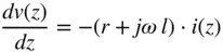
(1.74) 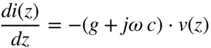
where v(z), i(z) are the voltage and current along the transmission line, and r, l, g, c are the resistance, inductance, conductance, and capacitance per unit length.
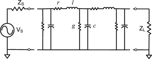
Figure 1.11 A transmission line modeled as distributed elements.
For a lossless cable, the impedance can be computed as simply
(1.75) 
but it becomes more complicated when loss is introduced, becoming
(1.76) 
In many applications, the conductance of the cable is negligible, particularly at low frequencies, so that the only loss element is the resistance per unit length, yielding
(1.77) 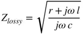
Inspection of Eq. (1.77)shows that the impedance of a cable must increase as the frequency goes down toward DC. Figure 1.12demonstrates this with a calculation the impedance of a nominal 75 Ω cable, with a 0.0001 Ω mm −1loss and capacitance of 0.07 pF mm −1(typical for RG 6 CATV coax). In this case, the impedance deviates from the expected value at 300 kHz by over 10 Ω; and by 1 Ω at 1 MHz.
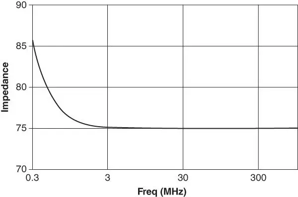
Figure 1.12 Impedance of a real transmission line at low frequency.
This low‐frequency response of impedance for any real transmission line is often unexpected by those unfamiliar with Eq. (1.77), and it is sometimes assumed that this is a result of measurement error. However, all real transmission lines must show such a low frequency characteristic, and verification methods must take into account this effect.
An “airline” coax consists of a cable with an air dielectric, sometimes supported by dielectric beads at either end or sometimes supported only by the center conductor of the adjacent connectors, as shown in Figure 1.13. This type of cable has virtually no conductance, so series resistive loss is the only loss element. The small white ring on the airline sometimes used to prevent sagging at the male end of the pin so that it may be more easily mated.
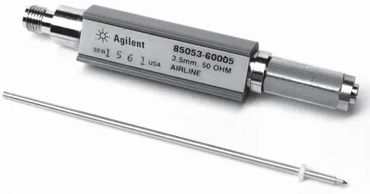
Figure 1.13 An airline coaxial transmission line.
Читать дальшеИнтервал:
Закладка:
Похожие книги на «Handbook of Microwave Component Measurements»
Представляем Вашему вниманию похожие книги на «Handbook of Microwave Component Measurements» списком для выбора. Мы отобрали схожую по названию и смыслу литературу в надежде предоставить читателям больше вариантов отыскать новые, интересные, ещё непрочитанные произведения.


Обсуждение, отзывы о книге «Handbook of Microwave Component Measurements» и просто собственные мнения читателей. Оставьте ваши комментарии, напишите, что Вы думаете о произведении, его смысле или главных героях. Укажите что конкретно понравилось, а что нет, и почему Вы так считаете.