Joel P. Dunsmore - Handbook of Microwave Component Measurements
Здесь есть возможность читать онлайн «Joel P. Dunsmore - Handbook of Microwave Component Measurements» — ознакомительный отрывок электронной книги совершенно бесплатно, а после прочтения отрывка купить полную версию. В некоторых случаях можно слушать аудио, скачать через торрент в формате fb2 и присутствует краткое содержание. Жанр: unrecognised, на английском языке. Описание произведения, (предисловие) а так же отзывы посетителей доступны на портале библиотеки ЛибКат.

- Название:Handbook of Microwave Component Measurements
- Автор:
- Жанр:
- Год:неизвестен
- ISBN:нет данных
- Рейтинг книги:5 / 5. Голосов: 1
-
Избранное:Добавить в избранное
- Отзывы:
-
Ваша оценка:
Handbook of Microwave Component Measurements: краткое содержание, описание и аннотация
Предлагаем к чтению аннотацию, описание, краткое содержание или предисловие (зависит от того, что написал сам автор книги «Handbook of Microwave Component Measurements»). Если вы не нашли необходимую информацию о книге — напишите в комментариях, мы постараемся отыскать её.
Handbook of Microwave Component Measurements — читать онлайн ознакомительный отрывок
Ниже представлен текст книги, разбитый по страницам. Система сохранения места последней прочитанной страницы, позволяет с удобством читать онлайн бесплатно книгу «Handbook of Microwave Component Measurements», без необходимости каждый раз заново искать на чём Вы остановились. Поставьте закладку, и сможете в любой момент перейти на страницу, на которой закончили чтение.
Интервал:
Закладка:
The commercial forms are found on a variety of devices and interconnect cables. The male version of these commercial‐grade parts present two common and distinct problems: there is often a rubber “weather‐seal” o‐ring in the base of the connector, and the outer nut of the male connector is knurled but has no flats to allow using a torque wrench. The first problem exacerbates the second, as the mating surface of the outer conductor of the male connector is often prevented from contacting the base of the female connector because the outer (supposedly non‐mating) surface of the female connector touches the rubber o‐ring and prevents the male outer conductor from making full contact. If one can fully torque a Type‐N connector, the rubber o‐ring would compress, and the contact of the male outer conductor would occur, but as there are no flats for a torque wrench, it is difficult to sufficiently torque the Type‐N connector to get good repeatable connections. This one issue is the cause of hundreds of hours of retest when components don't pass their return‐loss specs. The solution is quite simple: remove the rubber o‐ring from the base of the male connector, always, before any measurement. A pair of tweezers and a needle‐nose pliers are indispensable for the process of removing this annoying o‐ring. One will note that none of the precision versions of Type‐N connectors contains such an o‐ring. Figure 1.19shows some examples of Type‐N connectors; the upper two are commercial grade, and the lower two are precision grade. Figure 1.20shows the insertion loss measurement of a male‐to‐male Type‐N adapter mated to a female‐to‐female Type‐N adapter for a precision pair and a commercial‐grade pair, where the loss is normalized to the length of the adapter. The commercial‐grade pair is operational only to about 12 GHz, due to moding in the connector. The precision N is mode free beyond 18 GHz.
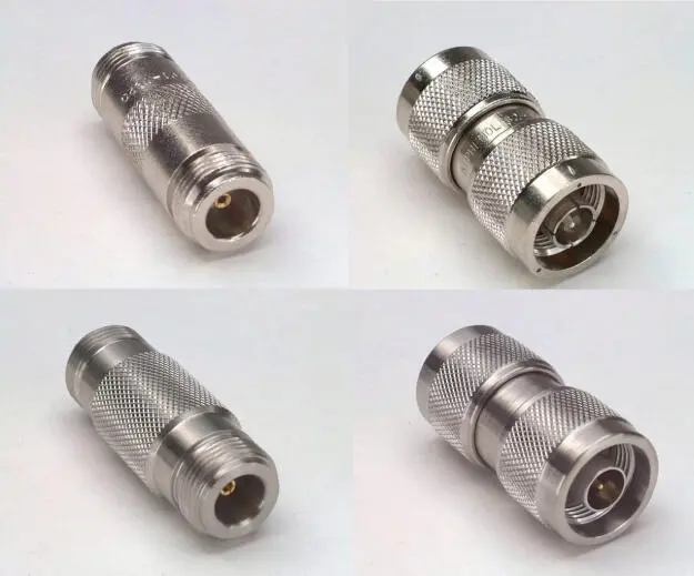
Figure 1.19 Examples of Type‐N connectors: commercial (upper) and precision (lower).
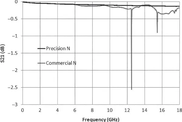
Figure 1.20 Performance of a precision and a standard Type‐N connector.
1.8.2.3 Type‐N 75 Ω Connector
Type‐N connectors also have a 75 Ω version, which has the same outer dimensions but a smaller center conductor. This is in some ways unfortunate as the smaller female collet of the 75 Ω version can be damaged when inserted with a 50 Ω male pin. There are a couple of versions of the 75 Ω female collet, one with short slots and six fingers, and one with long slots and four fingers. A precision slotless version is also available. The short slot version has the potential for better measurements, as the slots expand less so there is less uncertainty of the open capacitance. However, on many products with 75 Ω N‐connectors, the long slot connector is used; the long slots were designed to accept a 50 Ω male pin, at least for a few insertions, without damage. Often the 75 Ω components have an extra machined ring or line on the outer nut to help identify it. Versions of 75 Ω Type‐N connectors are shown in Figure 1.21. An example of the insertion loss measurement of a mated pair of a male‐to‐male adapter with a female‐to‐female adapter is shown in Figure 1.22, where the loss is normalized for length of the adapter. The frequency limit of Type‐N 75 is often stated as 2 or 3 GHz, but that is because the commercially available calibration kits were rated only to those frequencies. In practice, these connectors could be used up to 7 or 8 GHz without difficulty. The response of the commercial‐grade connector is likely limited not due to moding (since the loss signature is quite low Q) but rather due to poor impedance control in the center pin support bead, causing impedance mismatch.
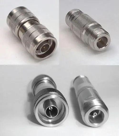
Figure 1.21 75 Ω Type‐N connectors: commercial (upper) and precision (lower).
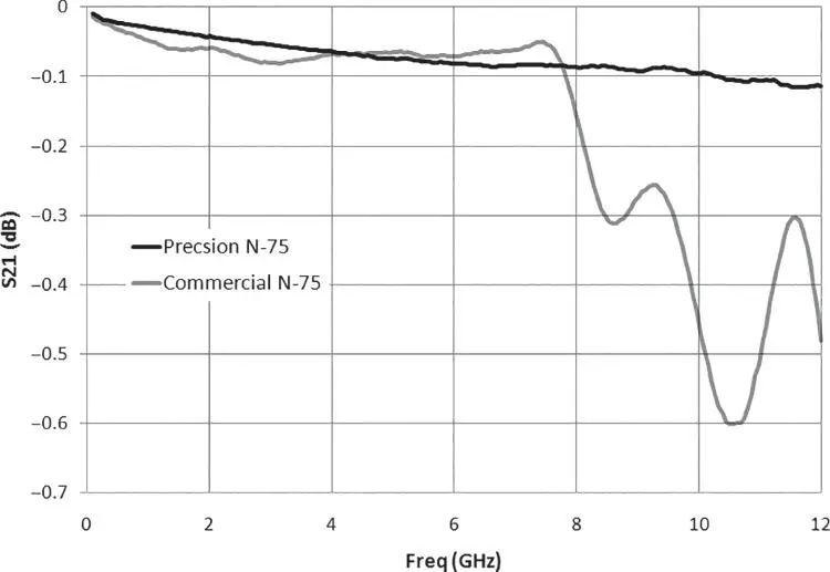
Figure 1.22 Insertion loss of 75 Ω connectors.
1.8.2.4 3.5 mm and SMA Connectors
The 3.5 mm connector is in essence half the scale of the N connector and provides higher‐frequency coverage. The center pin of the 3.5 mm connector is supported by a plastic bead, rather than solid dielectric, meaning it has mode‐free operation to a much higher frequency than Type‐N. Traditionally, 3.5 mm connectors are specified up to 26.5 GHz, but their first mode is nearly 30 GHz, and they are functional up to about 38 GHz. An interesting aspect of modes is that the first mode of a 3.5 mm connector is due to the bead (and its increased effective dielectric), but this mode is non‐propagating, so it is reasonable to use these connectors to even higher frequencies. The 3.5 mm female connector comes with several versions of center pin, the main varieties being a four‐slot collect and a slotless precision connection, found now on most calibration kits. Interestingly, even though the slotless connectors may have the center spring contact damaged due to oversized or misaligned male pins (under the microscope one or more fingers may be crushed back into the hollow of the female pin), the RF performance is almost unaffected due the robust solid outer conductor. In fact, one typically can tell if a slotless connector is damaged only by visual inspection, as the RF performance is substantially unchanged, as long as even one finger is left to make contact.
The SMA connector is mechanically compatible with the 3.5 mm connector but has a solid Teflon dielectric and thus a lower operating frequency due to moding. SMA is traditionally considered to be an 18 GHz connector, but the first propagating mode is well above 20 GHz, depending upon the type of cable that is connected to the SMA connector. The chief advantage of SMA connectors is low cost, especially when mounted to semi‐rigid coaxial cables. The dimensions are such that the center wire of the coax can be used a connector pin for SMA, and only an outer conductor sleeve needs to be added to the coax outer conductor to form a male connector, shown in the lower‐right picture of Figure 1.23. But these cables are notoriously bad at maintaining the proper dimensions for the center pin, and often the center pins are poorly trimmed and improperly chamfered so that they cause mating problems with their female counterparts. This is particularly true when mating them to 3.5 mm female connectors, slotless ones in particular. Figure 1.23shows examples of 3.5 mm and SMA connectors, with 3.5 mm on the left and SMA on the right.
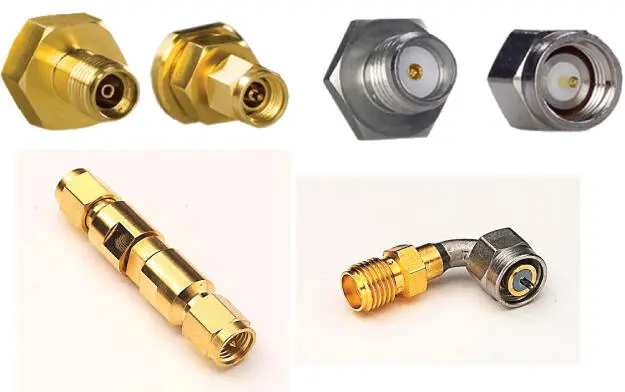
Figure 1.23 3.5 mm (f) and (m) (upper left); SMA (f) and (m) connectors (upper right); 3.5 mm (lower left) and SMA adapters (lower right).
Figure 1.24shows measurement plots of a mated pair of 3.5 mm male‐to‐male with a 3.5 mm female‐to‐female, as well as two SMA examples. The moding of the SMA connector is clearly seen above 25 GHz (Marker 2 on the SMA1 and SMA2 trace). The moding of the 3.5 mm connector is seen just above 30 GHz (Marker 2) and again at 34 and 38 GHz. There two typical construction types for SMA, one with a press‐fit of the Teflon and center conductor (SMA1 in the measured response) and one where the Teflon is held in with a small dot of epoxy through a hole in the outer conductor (SMA2 in the measured response). The second method usually gives a poorer match, and we can see that with the small dip in the S21 response of SMA2 near 12 GHz and the larger dip just above 20 GHz.
Читать дальшеИнтервал:
Закладка:
Похожие книги на «Handbook of Microwave Component Measurements»
Представляем Вашему вниманию похожие книги на «Handbook of Microwave Component Measurements» списком для выбора. Мы отобрали схожую по названию и смыслу литературу в надежде предоставить читателям больше вариантов отыскать новые, интересные, ещё непрочитанные произведения.


Обсуждение, отзывы о книге «Handbook of Microwave Component Measurements» и просто собственные мнения читателей. Оставьте ваши комментарии, напишите, что Вы думаете о произведении, его смысле или главных героях. Укажите что конкретно понравилось, а что нет, и почему Вы так считаете.