Joel P. Dunsmore - Handbook of Microwave Component Measurements
Здесь есть возможность читать онлайн «Joel P. Dunsmore - Handbook of Microwave Component Measurements» — ознакомительный отрывок электронной книги совершенно бесплатно, а после прочтения отрывка купить полную версию. В некоторых случаях можно слушать аудио, скачать через торрент в формате fb2 и присутствует краткое содержание. Жанр: unrecognised, на английском языке. Описание произведения, (предисловие) а так же отзывы посетителей доступны на портале библиотеки ЛибКат.

- Название:Handbook of Microwave Component Measurements
- Автор:
- Жанр:
- Год:неизвестен
- ISBN:нет данных
- Рейтинг книги:5 / 5. Голосов: 1
-
Избранное:Добавить в избранное
- Отзывы:
-
Ваша оценка:
Handbook of Microwave Component Measurements: краткое содержание, описание и аннотация
Предлагаем к чтению аннотацию, описание, краткое содержание или предисловие (зависит от того, что написал сам автор книги «Handbook of Microwave Component Measurements»). Если вы не нашли необходимую информацию о книге — напишите в комментариях, мы постараемся отыскать её.
Handbook of Microwave Component Measurements — читать онлайн ознакомительный отрывок
Ниже представлен текст книги, разбитый по страницам. Система сохранения места последней прочитанной страницы, позволяет с удобством читать онлайн бесплатно книгу «Handbook of Microwave Component Measurements», без необходимости каждый раз заново искать на чём Вы остановились. Поставьте закладку, и сможете в любой момент перейти на страницу, на которой закончили чтение.
Интервал:
Закладка:
1.8.3 Non‐coaxial Transmission Lines
Transmission lines provide the interconnection between components, typically in a microcircuit or a PC board. These are distinguished from a measurement perspective because they are typically much shorter, often not shielded, and the interface to them is not easy to make and sometimes not well defined. While there have been whole books written on the subject, a short review of some common transmission line structures and their attributes are described next, with a focus on attributes important to measurement. Transmission lines are characterized by the same three parameters: impedance, effective dielectric constant, and loss.
1.8.3.1 Microstrip
Certainly the most widespread transmission line must be the microstrip line, shown in Figure 1.30. This is found in planar structures such as PC boards and micro‐circuits. Consisting of a thin strip of metal on a dielectric substrate, over a ground plane, it is used for connection between components as well as creating transmission line components such as couplers and filters (Hong and Lancaster 2001).
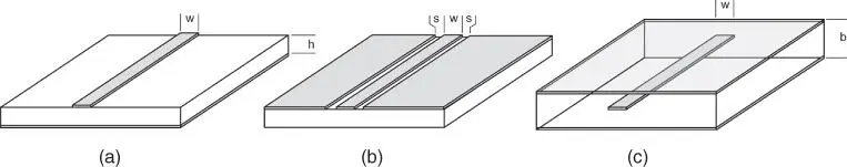
Figure 1.30 Planer transmission lines: microstrip (a), coplanar waveguide (b), strip line (c).
The computation of the transmission parameters has been fully documented in many forms, but for measurement purposes these lines are typically 50 Ω (or the equivalent system impedance) even though as a design element they can take on any value. For most applications, the dielectric constant is 10 or less, so the w/h ratio is greater than 1 for 50 Ω. The approximate impedance can be computed as (Pozar 1990)
(1.86) 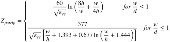
where ε reis the effective relative‐dielectric‐constant, found from
(1.87) 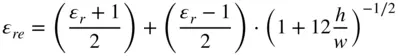
The effective relative‐dielectric constant sets the velocity factor of the transmission line, but in microstrip, some of the fields travel in the substrate and some in air. Therefore, the transmission is not purely transverse‐electromagnetic (TEM), and some structures become more difficult to design, particularly coupled lines, the even and odd mode velocity factors of which are not the equal. Since the line is not pure TEM, at high frequency, dispersion effects will become apparent where the effective delay of the line is not constant with frequency.
The loss of microstrip lines is difficult to compute accurately because it depends upon many factors including the conductivity of the microstrip line and the ground plan, the dielectric loss of the substrate, radiated loss to the housing or shield, and losses related to both surface roughness and edge roughness. These roughness losses can be significant in PC board and low‐temperature cofired‐ceramic (LTCC) applications and are dependent upon the particular processes used. While there are high‐quality PC board materials (Duriod™ or GTEK™ are common trade names), the material known as FR4 is most common, and the dielectric constant and loss of this PC board material can be uncertain. The finished substrate can be comprised of layers of board material sandwiched together with glue, and the final thickness can depend upon processing steps, so it is best when evaluating microstrip transmission lines to produce sample structures that can help determine the exact nature of the material.
One high‐performance material used is single‐crystal sapphire, and it has the unusual property of having a dielectric constant that has a directionality, with a higher constant of 10.4 in one of the three dimensions, and a lower constant of 9.8 in the other two. A second, common high‐performance dielectric is ceramic found in thin‐film, thick‐film, and LTCC applications. It has a uniform dielectric constant typically between 9.6 and 9.8 depending upon the purity and grain structure of the ceramic.
1.8.3.2 Other Quasi‐Microstrip Structures
For many applications, the size of 50 Ω microstrip line is not suitable for connections to very large devices. Some common modifications are suspended substrate microstrip line, where the ground plan has been removed some distance from the dielectric. This has the effect of lowering the effective dielectric constant and raising the impedance of the line. In this way, a wider line can be used to connect to a wide component and still maintain a matched impedance. A shielded microstrip line is entirely enclosed (the theoretical models of microstrip lines assume no top shield), and the top metal tends to lower the impedance of the line. This is particularly true for suspended microstrip lines.
1.8.3.3 Coplaner Waveguide
One difficulty with microstrip transmission lines is that the ground and signal conductors are on different physical planes. Coplanar waveguide (CPW), as the name implies, provides a coplanar structure of ground‐signal‐ground, as shown in Figure 1.30b. An alternative is grounded coplanar where the backside is a conductor as well, and in practice, all coplanar lines have associated package ground, but the ground may be ignored if there is a substantial air‐gap between the substrate and the package ground. The references provide some computations of coplanar waveguide impedance for various configurations (Wen 1969; Simons 2001). In microwave measurements, CPW is used extensively as a contacting means for on‐wafer measurements and is used to provide extremely low ground inductance for measuring microwave transistors and circuits, as shown in Figure 1.31, with either topside grounds (left) or backside grounds (right). Note that since the impedance depends only upon the scale of width to space, this allows contacts of large scale (such as probes) to be transitioned to small scale such as IC devices.
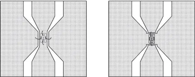
Figure 1.31 CPW‐mounted IC.
CPW has some inherent problems due to the ground being on a surface plane or sheet. In many instances the CPW line is mounted in a metal package, and the ground plane is grounded at the package wall. If the distance from the package wall to the ground plane edge approaches a quarter‐wavelength at the frequency of interest, or multiples thereof, then a transmission line mode can form such that the ground of the CPW appears as an open relative to the package ground. This concept of “hot grounds” for CPW has been observed in many situations and is sometimes avoided by periodically grounding one side to the other through a small cross connection on the backside of the CPW. Another method is to provide a lossy connection to the sidewall ground through absorptive material or thin film resist material to suppress energy in the unwanted mode. Another alternative is treating the CPW as a suspended substrate only under the gap between ground and conductor and “stitching” the CPW ground to the backside ground through a series of conductive vias. The impedance of these structures is lowered by the added ground, so an adjustment of the center line width is usually made to accommodate the additional ground paths.
Читать дальшеИнтервал:
Закладка:
Похожие книги на «Handbook of Microwave Component Measurements»
Представляем Вашему вниманию похожие книги на «Handbook of Microwave Component Measurements» списком для выбора. Мы отобрали схожую по названию и смыслу литературу в надежде предоставить читателям больше вариантов отыскать новые, интересные, ещё непрочитанные произведения.


Обсуждение, отзывы о книге «Handbook of Microwave Component Measurements» и просто собственные мнения читателей. Оставьте ваши комментарии, напишите, что Вы думаете о произведении, его смысле или главных героях. Укажите что конкретно понравилось, а что нет, и почему Вы так считаете.