Joel P. Dunsmore - Handbook of Microwave Component Measurements
Здесь есть возможность читать онлайн «Joel P. Dunsmore - Handbook of Microwave Component Measurements» — ознакомительный отрывок электронной книги совершенно бесплатно, а после прочтения отрывка купить полную версию. В некоторых случаях можно слушать аудио, скачать через торрент в формате fb2 и присутствует краткое содержание. Жанр: unrecognised, на английском языке. Описание произведения, (предисловие) а так же отзывы посетителей доступны на портале библиотеки ЛибКат.

- Название:Handbook of Microwave Component Measurements
- Автор:
- Жанр:
- Год:неизвестен
- ISBN:нет данных
- Рейтинг книги:5 / 5. Голосов: 1
-
Избранное:Добавить в избранное
- Отзывы:
-
Ваша оценка:
Handbook of Microwave Component Measurements: краткое содержание, описание и аннотация
Предлагаем к чтению аннотацию, описание, краткое содержание или предисловие (зависит от того, что написал сам автор книги «Handbook of Microwave Component Measurements»). Если вы не нашли необходимую информацию о книге — напишите в комментариях, мы постараемся отыскать её.
Handbook of Microwave Component Measurements — читать онлайн ознакомительный отрывок
Ниже представлен текст книги, разбитый по страницам. Система сохранения места последней прочитанной страницы, позволяет с удобством читать онлайн бесплатно книгу «Handbook of Microwave Component Measurements», без необходимости каждый раз заново искать на чём Вы остановились. Поставьте закладку, и сможете в любой момент перейти на страницу, на которой закончили чтение.
Интервал:
Закладка:
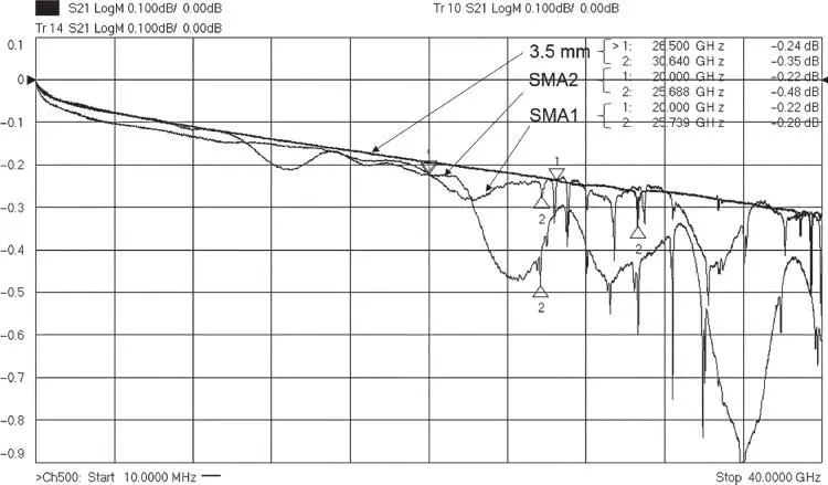
Figure 1.24 Performance of SMA and 3.5 mm mated‐pair connectors.
1.8.2.5 2.92 mm Connector
The 2.92 mm connector is scaled down from the 3.5 mm connector and can be mechanically mated to both the 3.5 mm and the SMA connectors. The smaller diameter outer conductor means that its mode‐free operation extends proportionally higher, to 40 GHz, and is usable to perhaps 46 GHz. The female connector has a two‐slot collet that provides sufficient compliance to mate with the center pin of the larger 3.5 mm and SMA connectors but that makes it less suitable for precision measurements due to increased uncertainty of the contact point on the center pin radius, which now depends upon the radius of the pin that is inserted. A further point is that the metal wall of the female collet on the 2.92 connector is quite thin and prone to damage if the mating pin is not well aligned or oversize. It's not uncommon to find 2.92 female adapters missing one of the collet fingers. The 2.92 mm connector was popularized by the Anristu company (formally Wiltron), which introduced it as the K connector, and it is common to hear any 2.92 mm connectors referred to by that name.
Figure 1.25shows some examples of 2.92 connectors. The key difference is in the diameter of the inside of the outer conductor. Figure 1.26shows the insertion loss of a mated pair of 2.92 mm female‐to‐female adapters with a 2.92 male‐to‐male adapter, along with an example of a 3.5 mm mated adapter pair. The moding of the 3.5 mm pair is clearly seen above 30 GHz, but the connector is generally usable up to 38 GHz as the first small modes are bead modes and are able to be calibrated out as they generally don't propagate through the cable.
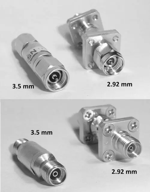
Figure 1.25 A 3.5 mm connector compared with 2.92 mm female (upper) and male (lower).
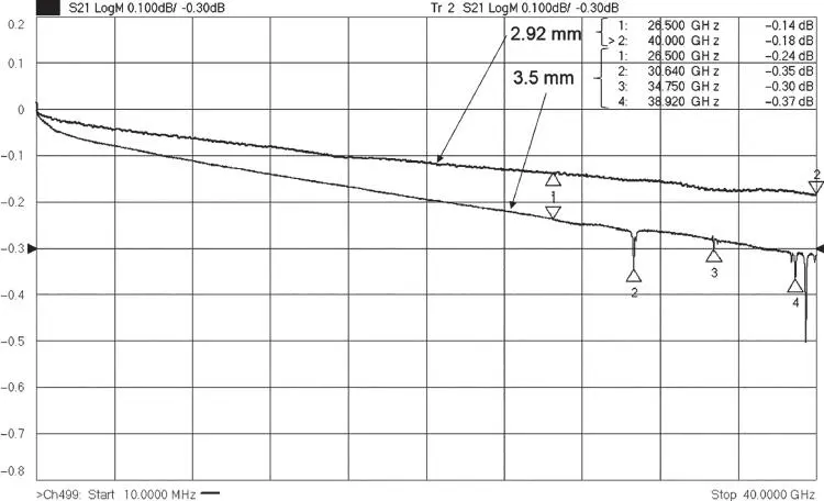
Figure 1.26 Performance of a mated pair, 2.92 compared with 3.5 mm.
1.8.2.6 2.4 mm Connector
The 2.4 mm connector is essentially a scaled version of the 3.5 mm connector, with an associated scaling in maximum frequency. It is used extensively on 50 GHz applications, though it can be used up to 60 GHz. This connector cannot be mated to any of the SMA, 3.5 mm or 2.92, and in fact was designed to prevent damage if one tried to mate to these types. It comes with both slotted and slotless female center pins, much like the 3.5 mm connector.
1.8.2.7 1.85 mm Connectors
There are two variants of the 1.85 mm connectors, designed originally by Anritsu and Agilent. The Anritsu variety is called the V connector, and the Agilent variety is called the 1.85 mm connector. They are mechanically compatible and were originally designed for 67 GHz operation, usable to above 75 GHz. These connectors are mechanically compatible with the 2.4 mm connector. Figure 1.27shows the wideband response to 85 GHz of the 1.85 mm connector in the upper plot and a zoomed‐in view of the first mode in the lower plot. This first mode is a “bead‐mode” and is caused by the increased dielectric constant of the bead, which holds the center pin, lowering the first mode of the 1.85 mm coaxial line. In general, this mode is non‐propagating (since it is contained in the bead) and may be calibrated out in some circumstances. For example, if this connector is used with an on‐wafer probe and the coax from the connector to the probe‐tip is mode free, then the bead mode will act like a small, stationary resonance that can be removed with a calibration. If the mode is propagating, then changes in the termination impedance change the effects of the mode, and it cannot be calibrated out (it is not stationary with respect to an external impedance); but if it is non‐propagating and there is a sufficient length of mode‐free line (such a cable) between this bead mode and the reference plane, the evanescent fields associated with the mode will die off before arriving at the reference plane and thus will not couple to the terminating impedance. As this first mode is less than 0.2 dB, in many cases it is not significant. The 1.85 mm connector has been used out past 75 GHz.
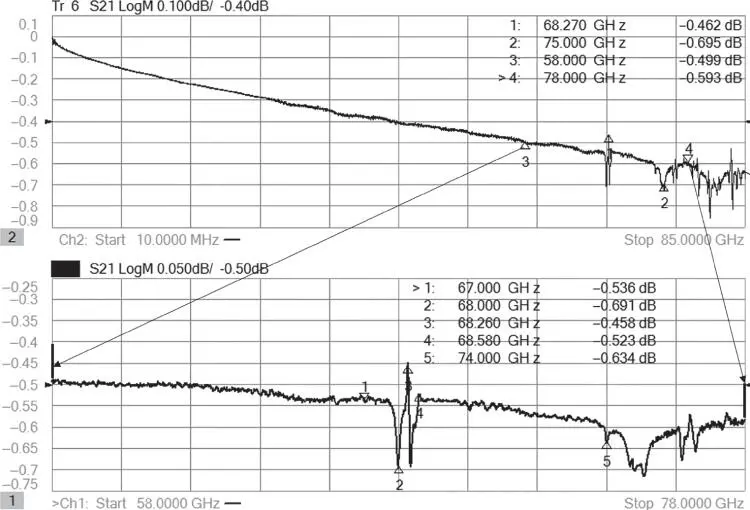
Figure 1.27 Response of mated pair of male‐to‐male and female‐to‐female 1.85 mm connectors (upper), with zoomed‐in view of the first mode (lower).
1.8.2.8 1 mm Connector
The 1 mm connector is essentially a scaled version of the 1.85 mm connector but cannot be mated to it. It is typically specified to 110 GHz performance but is usable to above 120 GHz, with some versions being specified up to 120 GHz and used up to 140 GHz. Figure 1.28shows the response of a mated pair of 1 mm male‐to‐male and female‐to‐female adapters (right scale) along with the same 1.85 mm mated pair of Figure 1.27(left scale). The reference line is offset by 1 division to make it easier to see the traces; without the offset, the traces would lie nearly on top of each other. The mode for 1 mm is a bit of a deeper mode but is now out past 120 GHz. There is a second mode at 124 GHz, but both are also non‐propagating, so it may be possible to remove them with calibration. The depth of the mode does imply that it may be from the multiple beads in the mated pair and not be very stable with changes in temperature.
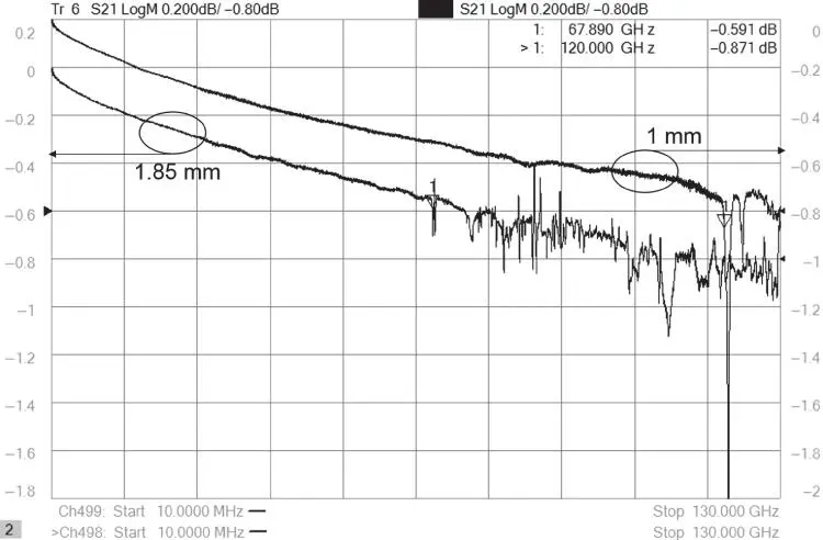
Figure 1.28 Response of a 1 mm mated pair and a 1.85 mm mated pair.
1.8.2.9 PC Board Launches and Cable Connectors
For many design and measurement applications, the circuit of interest is embedded in a PC board. There are many types and styles of PC board launches, which typically have an SMA connector on one end and PC board contacts at the other, as well as miniature versions such as the QMA connector. These can come in edge launch as well as right angle, and their performance depends greatly upon the mounting pattern on the PC board trace. These can be difficult to characterize because only one end is available in a standard connector. An example of a common PC board launch is shown in Figure 1.29. Measurement techniques for these devices, as well as methods to remove their effects from the measurement of on‐board PC components, are discussed in Chapter 11.
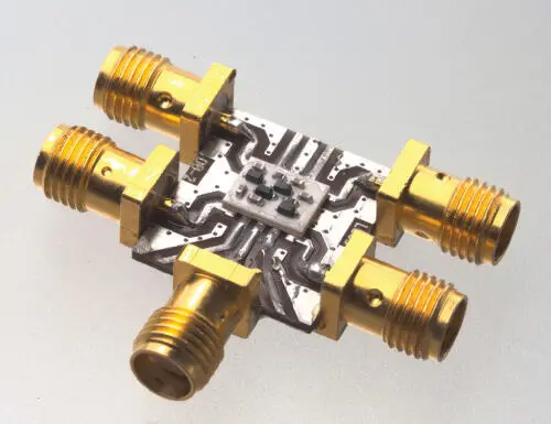
Figure 1.29 PC board SMC launches.
Connectors designed for coaxial‐cables provide similar challenges, as the cable to which they are attached affects the quality of the connection, and the common practice of attaching two connectors to each end of cable makes it difficult to separate the effects of one from the other. Time‐domain techniques can be applied to remove these unwanted effects, as described in Chapter 5.
Читать дальшеИнтервал:
Закладка:
Похожие книги на «Handbook of Microwave Component Measurements»
Представляем Вашему вниманию похожие книги на «Handbook of Microwave Component Measurements» списком для выбора. Мы отобрали схожую по названию и смыслу литературу в надежде предоставить читателям больше вариантов отыскать новые, интересные, ещё непрочитанные произведения.


Обсуждение, отзывы о книге «Handbook of Microwave Component Measurements» и просто собственные мнения читателей. Оставьте ваши комментарии, напишите, что Вы думаете о произведении, его смысле или главных героях. Укажите что конкретно понравилось, а что нет, и почему Вы так считаете.