Joel P. Dunsmore - Handbook of Microwave Component Measurements
Здесь есть возможность читать онлайн «Joel P. Dunsmore - Handbook of Microwave Component Measurements» — ознакомительный отрывок электронной книги совершенно бесплатно, а после прочтения отрывка купить полную версию. В некоторых случаях можно слушать аудио, скачать через торрент в формате fb2 и присутствует краткое содержание. Жанр: unrecognised, на английском языке. Описание произведения, (предисловие) а так же отзывы посетителей доступны на портале библиотеки ЛибКат.

- Название:Handbook of Microwave Component Measurements
- Автор:
- Жанр:
- Год:неизвестен
- ISBN:нет данных
- Рейтинг книги:5 / 5. Голосов: 1
-
Избранное:Добавить в избранное
- Отзывы:
-
Ваша оценка:
Handbook of Microwave Component Measurements: краткое содержание, описание и аннотация
Предлагаем к чтению аннотацию, описание, краткое содержание или предисловие (зависит от того, что написал сам автор книги «Handbook of Microwave Component Measurements»). Если вы не нашли необходимую информацию о книге — напишите в комментариях, мы постараемся отыскать её.
Handbook of Microwave Component Measurements — читать онлайн ознакомительный отрывок
Ниже представлен текст книги, разбитый по страницам. Система сохранения места последней прочитанной страницы, позволяет с удобством читать онлайн бесплатно книгу «Handbook of Microwave Component Measurements», без необходимости каждый раз заново искать на чём Вы остановились. Поставьте закладку, и сможете в любой момент перейти на страницу, на которой закончили чтение.
Интервал:
Закладка:
So computing power gain as in Eq. (1.37)and converting to dB yields the familiar formula
(1.39) 
A few more comments on power are appropriate, as power has several common meanings that can be confused if not used carefully. For any given source, as shown in Figure 1.1, there exists a load for which the maximum power of the source may be delivered to that load. This maximum power occurs when the impedance of the load is equal to the conjugate of the impedance of the source, and the maximum power delivered is
(1.40) 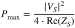
But it is instructive to note that the maximum power as defined in Eq. (1.40)is the same as | a 1| 2provided the source impedance is real and equals the reference impedance; thus, the incident power from a Z 0source is always the maximum power that can be delivered to a load. The actual power delivered to the load can be defined in terms of a and b waves as well.
(1.41) 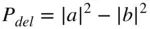
If one considers a passive two‐port network and conservation of energy, power delivered to the load must be less than or equal to the power incident on the network minus the power reflected, or in terms of S‐parameters
(1.42) 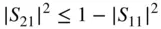
which leads the well‐known formula for a lossless network
(1.43) 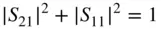
1.3.2 Phase Response of Networks
While most of the discussion thus far about S‐parameters refers to powers, including incident, reflected, and delivered to the load, the S‐parameters are truly complex numbers and contain both a magnitude and phase component. For reflection measurements, the phase component is critically important and provides insight into the input elements of the network. These will be discussed in great detail as part of Chapter 2, especially when referencing the Smith chart.
For transmission measurements, the magnitude response is often the most cited value of a system, but in many communications systems, the phase response has taken on more importance. The phase response of a network is typically given by
(1.44) 
where the region of the arctangent is usually chosen to be ±180°. However, it is sometimes preferable to display the phase in absolute terms, such that there are no phase discontinuities in the displayed value. This is sometimes called the unwrapped phase, in which the particular cycle of the arctangent must be determined from the previous cycle, starting from the DC value. Thus, the unwrapped phase is uniquely defined for an S 21response only when it includes all values down to zero frequency (DC).
The linearity of the phase response has consequences when looking at its effect on complex modulated signals. In particular, it is sometimes stated that linear networks cannot cause distortion, but this is true only of single‐frequency sinusoidal inputs. Linear networks can cause distortion in the envelope of complex modulated signals, even if the frequency response (the magnitude of S 21) is flat. That is because the phase response of a network directly affects the relative time that various frequencies of a complex modulated signal take to pass through the network. Consider the signal in Figure 1.4.
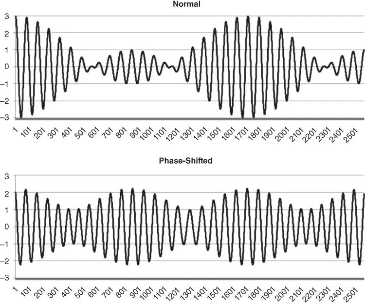
Figure 1.4 Modulated signal through a network showing distortion due to only phase shift: normal (upper), shifted (lower).
For this network, the phase of S 21defines how much shift occurs for each frequency element in the modulated signal. Even though the amplitude response is the same in both Figure 1.4a,b, the phase response is different, and the envelope of the resulting output is changed. In general, there is some delay from the input to the output of a network, and the important definition that is most commonly used is the group delay of the network, defined as
(1.45) 
While easily defined, the group delay response may be difficult to measure and/or interpret. This is because measurement instruments record discrete values for phase, and the group delay is a derivative of the phase response. Using discrete differentiation can generate numerical difficulties; Chapter 5shows some of the difficulties encountered in practice when measuring group delay, as well as some solutions to these difficulties.
For most complex signals, the ideal goal for phase response of a network is that of a linear phase response. Deviation from linear phase is a figure of merit for the phase flatness of a network, and this is closely related another figure of merit, group delay flatness. Thus, the ideal network has a flat group delay, meaning a linear phase response. However, many complex communications systems employ equalization to remove some of the phase response effects. Often, this equalization can account for first‐ or second‐order deviations in the phase; thus, another figure of merit is deviation from parabolic phase, which is effectively a measure of the quality of fit of the phase response to a second order polynomial. These measurements are discussed further in Chapter 5.
1.4 Power Parameters
1.4.1 Incident and Reflected Power
Just as there are a variety of S‐parameters, which are derived from the fundamental parameters of incident and reflected waves a and b , so too are there many power parameters that can be identified with the same waves. As inferred earlier, the principal power parameters are incident and reflected, or forward and reverse, powers at each port, which for Z 0real, are defined as
(1.46) 
The proper interpretation of these parameters is that incident and reflected power is the power that would be delivered to a nonreflecting ( Z 0) load. If one were to put an ideal Z 0directional‐coupler in line with the signal, it would sample or couple the incident signal (if the coupler were set to couple the forward power) or the reflected signal (if the coupler were set to couple the reverse power). In simulations, ideal directional‐couplers are often used in just such a manner.
1.4.2 Available Power
The maximum power that can delivered from a generator is called the available power , or P Available, and can be defined as the power delivered from a Z S
Читать дальшеИнтервал:
Закладка:
Похожие книги на «Handbook of Microwave Component Measurements»
Представляем Вашему вниманию похожие книги на «Handbook of Microwave Component Measurements» списком для выбора. Мы отобрали схожую по названию и смыслу литературу в надежде предоставить читателям больше вариантов отыскать новые, интересные, ещё непрочитанные произведения.


Обсуждение, отзывы о книге «Handbook of Microwave Component Measurements» и просто собственные мнения читателей. Оставьте ваши комментарии, напишите, что Вы думаете о произведении, его смысле или главных героях. Укажите что конкретно понравилось, а что нет, и почему Вы так считаете.