Joel P. Dunsmore - Handbook of Microwave Component Measurements
Здесь есть возможность читать онлайн «Joel P. Dunsmore - Handbook of Microwave Component Measurements» — ознакомительный отрывок электронной книги совершенно бесплатно, а после прочтения отрывка купить полную версию. В некоторых случаях можно слушать аудио, скачать через торрент в формате fb2 и присутствует краткое содержание. Жанр: unrecognised, на английском языке. Описание произведения, (предисловие) а так же отзывы посетителей доступны на портале библиотеки ЛибКат.

- Название:Handbook of Microwave Component Measurements
- Автор:
- Жанр:
- Год:неизвестен
- ISBN:нет данных
- Рейтинг книги:5 / 5. Голосов: 1
-
Избранное:Добавить в избранное
- Отзывы:
-
Ваша оценка:
Handbook of Microwave Component Measurements: краткое содержание, описание и аннотация
Предлагаем к чтению аннотацию, описание, краткое содержание или предисловие (зависит от того, что написал сам автор книги «Handbook of Microwave Component Measurements»). Если вы не нашли необходимую информацию о книге — напишите в комментариях, мы постараемся отыскать её.
Handbook of Microwave Component Measurements — читать онлайн ознакомительный отрывок
Ниже представлен текст книги, разбитый по страницам. Система сохранения места последней прочитанной страницы, позволяет с удобством читать онлайн бесплатно книгу «Handbook of Microwave Component Measurements», без необходимости каждый раз заново искать на чём Вы остановились. Поставьте закладку, и сможете в любой момент перейти на страницу, на которой закончили чтение.
Интервал:
Закладка:
(1.13) 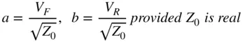
Or, more formally as a power wave definition
(1.14) 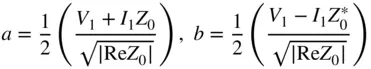
where Eq. (1.14)includes the situation in which Z 0is not pure real (Kurokawa 1965). However, it would be an unusual case to have a complex reference impedance in any practical measurement.
For real values of Z 0, one can define the forward or incident power as  and the reverse or scattered power as
  and see that the values a and b are related to the forward and reverse voltage waves, but with the units of square root of power. In practice, the definition of Eq. (1.13)is typically used, as the definition of Z 0is almost always either 50 or 75 Ω. In the case of waveguide measurements, the impedance is not well defined and changes with frequency and waveguide type. It is recommended to simply use a normalized impedance of 1 for the waveguide impedance. This does not represent 1 Ω but is used to represent the fact that measurements in a waveguide are normalized to the impedance of an ideal waveguide. In Eq. (1.13)incident and reflected waves are defined, and in practice the incident waves are the independent variables, and the reflected waves are the dependent variables. Consider Figure 1.2, a 2‐port network.
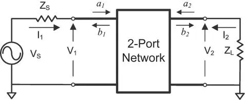
Figure 1.2 2‐port network connected to a source and load.
There are now sets of incident and reflected waves at each port i , where
(1.15) 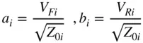
The voltages and currents at each port can now be defined as
(1.16) 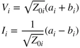
where Z 0iis the reference impedance for the i th port. An important point here that is often misunderstood is that the reference impedance does not have to be the same as the port impedance or the impedance of the network. It is a “nominal” impedance; that is, it is the impedance that we “name” when we are determining the S‐parameters, but it need not be associated with any impedance in the circuit. Thus, a 50 Ω test system can easily measure and display S‐parameters for a 75 Ω device, referenced to 75 Ω.
The etymology of the term reflected derives from optics and refers to light reflecting off a lens or other object with an index of refraction different from air, whereas it appears that the genesis for the scattering or S‐matrix was derived in the study of particle physics, from the concept of wavelike particles scattering off crystals. In microwave work, scattering or S‐parameters are defined to relate the independent incident waves to the dependent waves; for a 2‐port network they become
(1.17) 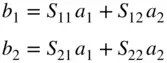
which can be placed in matrix form as
(1.18) 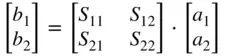
where a's represent the incident power at each port, that is, the power flowing into the port, and b's represent the scattered power, that is, the power reflected or emanating from each port. For more than two ports, the matrix can be generalized to
(1.19) 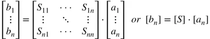
From Eq. (1.17)it is clear that it takes four parameters to relate the incident waves to the reflected waves, but Eq. (1.17)provides only two equations. As a consequence, solving for the S‐parameters of a network requires that at least two sets of linearly independent conditions for a 1and a 2be applied, and the most common set is one where first a 2is set to zero, the resulting b waves are measured, and then a 1is set to zero, and finally a second set of b waves are measured. This yields
(1.20) 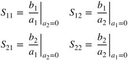
which is the most common expression of S‐parameter values as a function of a and b waves, and often the only one given for their definition. However, there is nothing in the definition of S‐parameters that requires one or the other incident signals to be zero, and it would be just as valid to define them in terms of two sets of incident signals, a nand  , and reflected signals, b nand
  .
.
(1.21) 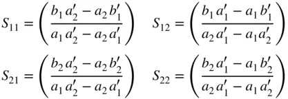
From Eq. (1.21)one sees that S‐parameters are in general defined for a pair of stimulus drives. This will become quite important in more advanced measurements and in the actual realization of the measurement of S‐parameters, because in practice it is not possible to make the incident signal go to zero because of mismatches in the measurement system.
These definitions naturally lead to the concept that S nnparameters are reflection coefficients and are directly related to the DUT port input impedance and S mnparameters are transmission coefficients and are directly related to the DUT gain or loss from one port to another.
Now that the S‐parameters are defined, they can be related to common terms used in the industry. Consider the circuit of Figure 1.3, where the load impedance Z Lmay be arbitrary and the source impedance is the reference impedance.
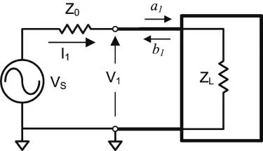
Figure 1.3 1‐port network.
From inspection one can see that
(1.22) 
Интервал:
Закладка:
Похожие книги на «Handbook of Microwave Component Measurements»
Представляем Вашему вниманию похожие книги на «Handbook of Microwave Component Measurements» списком для выбора. Мы отобрали схожую по названию и смыслу литературу в надежде предоставить читателям больше вариантов отыскать новые, интересные, ещё непрочитанные произведения.


Обсуждение, отзывы о книге «Handbook of Microwave Component Measurements» и просто собственные мнения читателей. Оставьте ваши комментарии, напишите, что Вы думаете о произведении, его смысле или главных героях. Укажите что конкретно понравилось, а что нет, и почему Вы так считаете.