Joel P. Dunsmore - Handbook of Microwave Component Measurements
Здесь есть возможность читать онлайн «Joel P. Dunsmore - Handbook of Microwave Component Measurements» — ознакомительный отрывок электронной книги совершенно бесплатно, а после прочтения отрывка купить полную версию. В некоторых случаях можно слушать аудио, скачать через торрент в формате fb2 и присутствует краткое содержание. Жанр: unrecognised, на английском языке. Описание произведения, (предисловие) а так же отзывы посетителей доступны на портале библиотеки ЛибКат.

- Название:Handbook of Microwave Component Measurements
- Автор:
- Жанр:
- Год:неизвестен
- ISBN:нет данных
- Рейтинг книги:5 / 5. Голосов: 1
-
Избранное:Добавить в избранное
- Отзывы:
-
Ваша оценка:
Handbook of Microwave Component Measurements: краткое содержание, описание и аннотация
Предлагаем к чтению аннотацию, описание, краткое содержание или предисловие (зависит от того, что написал сам автор книги «Handbook of Microwave Component Measurements»). Если вы не нашли необходимую информацию о книге — напишите в комментариях, мы постараемся отыскать её.
Handbook of Microwave Component Measurements — читать онлайн ознакомительный отрывок
Ниже представлен текст книги, разбитый по страницам. Система сохранения места последней прочитанной страницы, позволяет с удобством читать онлайн бесплатно книгу «Handbook of Microwave Component Measurements», без необходимости каждый раз заново искать на чём Вы остановились. Поставьте закладку, и сможете в любой момент перейти на страницу, на которой закончили чтение.
Интервал:
Закладка:
1.3 Definition of Microwave Parameters
In this section, many of the relevant parameters used in microwave components are derived from the fundamental measurements of voltage and current on the ports. For simplicity, the derivations will focus on measurements made under the conditions of termination in real valued impedances, with the goal of providing mathematical derivations that are straightforward to follow and readily applicable to practical cases.
In microwave measurements, the fundamental parameter of measurement is power. One of the key goals of microwave circuit design is to optimize the power transfer from one circuit to another such as from an amplifier to an antenna. In the microwave world, power is almost always referred to as either an incident power or a reflected power, in the context of power traveling along a transmission structure. The concept of traveling waves is of fundamental importance to understanding microwave measurements, and to engineers who haven't had a course on transmission lines and traveling waves, and even some who have, the concept of power flow and traveling waves can be confusing.
1.3.1 S‐Parameter Primer
S‐parameters have been developed in the context of microwave measurements but have a clear relationship to voltages and currents that are the common reference for most electrical engineers. This section will develop the definition of traveling waves and from that the definition of S‐parameters, in a way that is both rigorous and ideally intuitive; the development will be incremental, rather than just quoting results, in hopes of engendering an intuitive understanding.
This signal traveling along a transmission line is known as a traveling wave (Marks and Williams 1992) and has a forward component and a reverse component. Figure 1.1shows the schematic of a two‐wire transmission structure with a source and a load.
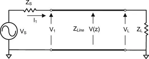
Figure 1.1 Voltage source and two‐wire system.
If the voltage from the source is sinusoidal, it is represented by the phasor notation
(1.1) 
The voltage and current at the load are
(1.2) 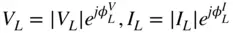
The voltage along the line is defined as V ( z ), and the current at each point is I ( z ). The impedance of the transmission line provides for a relationship between the voltage and the current. At the reference point, the total voltage is V (0) and is equal to V 1; the total current is I (0). The power delivered to the load can be described as
(1.3) 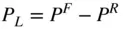
where P Fis called the forward power , and P Ris called the reverse power . To put this in terms of the voltage and current of Figure 1.1, the total voltage at the port can be defined as the sum of the forward voltage wave traveling into the port and the reverse voltage wave emerging from the port.
(1.4) 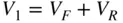
The forward voltage wave represents a power traveling toward the load, or transferring from the source to the load, and the reflected voltage wave represents power traveling toward the source. To be formal, for a sinusoidal voltage source, the voltage as a function of time is
(1.5) 
From this it is clear that  is the peak voltage and the root‐mean‐square (rms) voltage is
(1.6) 
The  factor shows often in the following discussion of power in a wave, and it is sometimes a point of confusion; but if one remembers that rms voltage is what is used to compute power in a sine wave, and is used to refer to the wave amplitude of a sine wave in the following equations, then it will make perfect sense.
Considering the source impedance Z Sand the line or port impedance Z 0, and simplifying a little by making Z S= Z 0and considering the case where Z 0is pure‐real, one can relate the forward and reverse voltage to an equivalent power wave. If one looks at the reference point of Figure 1.1and one had the possibility to insert a current probe as well as had a voltage probe, one could monitor the voltage and current.
The source voltage must equal the sum of the voltage at port 1 and the voltage drop of the current flowing through the source impedance.
(1.7) 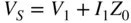
Defining the forward voltage as
(1.8) 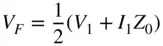
we see that the forward voltage represents the voltage at port 1 in the case where the termination is Z 0. From this and Eq. (1.4), one finds that the reverse voltage must be
(1.9) 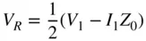
If the transmission line in Figure 1.1is long (such that the load effect is not noticeable) and the line impedance at the reference point is the same as the source, which may be called the port reference impedance, then the instantaneous current going into the transmission line is
(1.10) 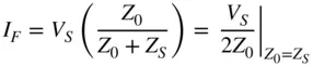
The voltage at that point is same as the forward voltage and can be found to be
(1.11) 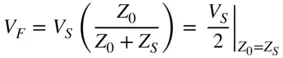
The power delivered to the line (or a Z 0load) is
(1.12) 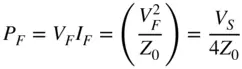
From these definitions, one can now refer to the incident and reflected power waves using the normalized incident and reflected voltage waves , a and b as (Keysight Technologies 1968).
Читать дальшеИнтервал:
Закладка:
Похожие книги на «Handbook of Microwave Component Measurements»
Представляем Вашему вниманию похожие книги на «Handbook of Microwave Component Measurements» списком для выбора. Мы отобрали схожую по названию и смыслу литературу в надежде предоставить читателям больше вариантов отыскать новые, интересные, ещё непрочитанные произведения.


Обсуждение, отзывы о книге «Handbook of Microwave Component Measurements» и просто собственные мнения читателей. Оставьте ваши комментарии, напишите, что Вы думаете о произведении, его смысле или главных героях. Укажите что конкретно понравилось, а что нет, и почему Вы так считаете.