Fundamentals of Terahertz Devices and Applications
Здесь есть возможность читать онлайн «Fundamentals of Terahertz Devices and Applications» — ознакомительный отрывок электронной книги совершенно бесплатно, а после прочтения отрывка купить полную версию. В некоторых случаях можно слушать аудио, скачать через торрент в формате fb2 и присутствует краткое содержание. Жанр: unrecognised, на английском языке. Описание произведения, (предисловие) а так же отзывы посетителей доступны на портале библиотеки ЛибКат.
- Название:Fundamentals of Terahertz Devices and Applications
- Автор:
- Жанр:
- Год:неизвестен
- ISBN:нет данных
- Рейтинг книги:4 / 5. Голосов: 1
-
Избранное:Добавить в избранное
- Отзывы:
-
Ваша оценка:
Fundamentals of Terahertz Devices and Applications: краткое содержание, описание и аннотация
Предлагаем к чтению аннотацию, описание, краткое содержание или предисловие (зависит от того, что написал сам автор книги «Fundamentals of Terahertz Devices and Applications»). Если вы не нашли необходимую информацию о книге — напишите в комментариях, мы постараемся отыскать её.
Fundamentals of Terahertz Devices and Applications
Fundamentals of Terahertz Devices and Applications — читать онлайн ознакомительный отрывок
Ниже представлен текст книги, разбитый по страницам. Система сохранения места последней прочитанной страницы, позволяет с удобством читать онлайн бесплатно книгу «Fundamentals of Terahertz Devices and Applications», без необходимости каждый раз заново искать на чём Вы остановились. Поставьте закладку, и сможете в любой момент перейти на страницу, на которой закончили чтение.
Интервал:
Закладка:
(2.69) 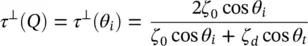
(2.70) 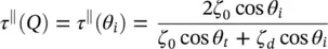
where 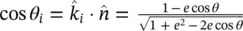 . Similarly, the transmission coefficients can be obtained from the reflection coefficients τ ⊥= 1 + Γ ⊥and
  . Thus, they are represented as:
Note that the angle of refraction θ tincreases as the incident angle θ iinside of the lens increases ( θ t> θ i). Total internal reflection ( Γ = 1) occurs when the angle of refraction is 90° and an incident angle known as the critical angle  . After this angle there is no transmission, therefore, this angle defines the domain of the equivalent aperture. As this angle lies at the center distance between the two focuses, the radius of the equivalent aperture is therefore the minor axis b . The incident angle that creates zero reflection in the parallel reflection coefficient is called Brewster's angle. An example of the reflection and transmission coefficients for a lens made in silicon are shown in Figure 2.27a and b, illustrating the critical and Brewster angles.
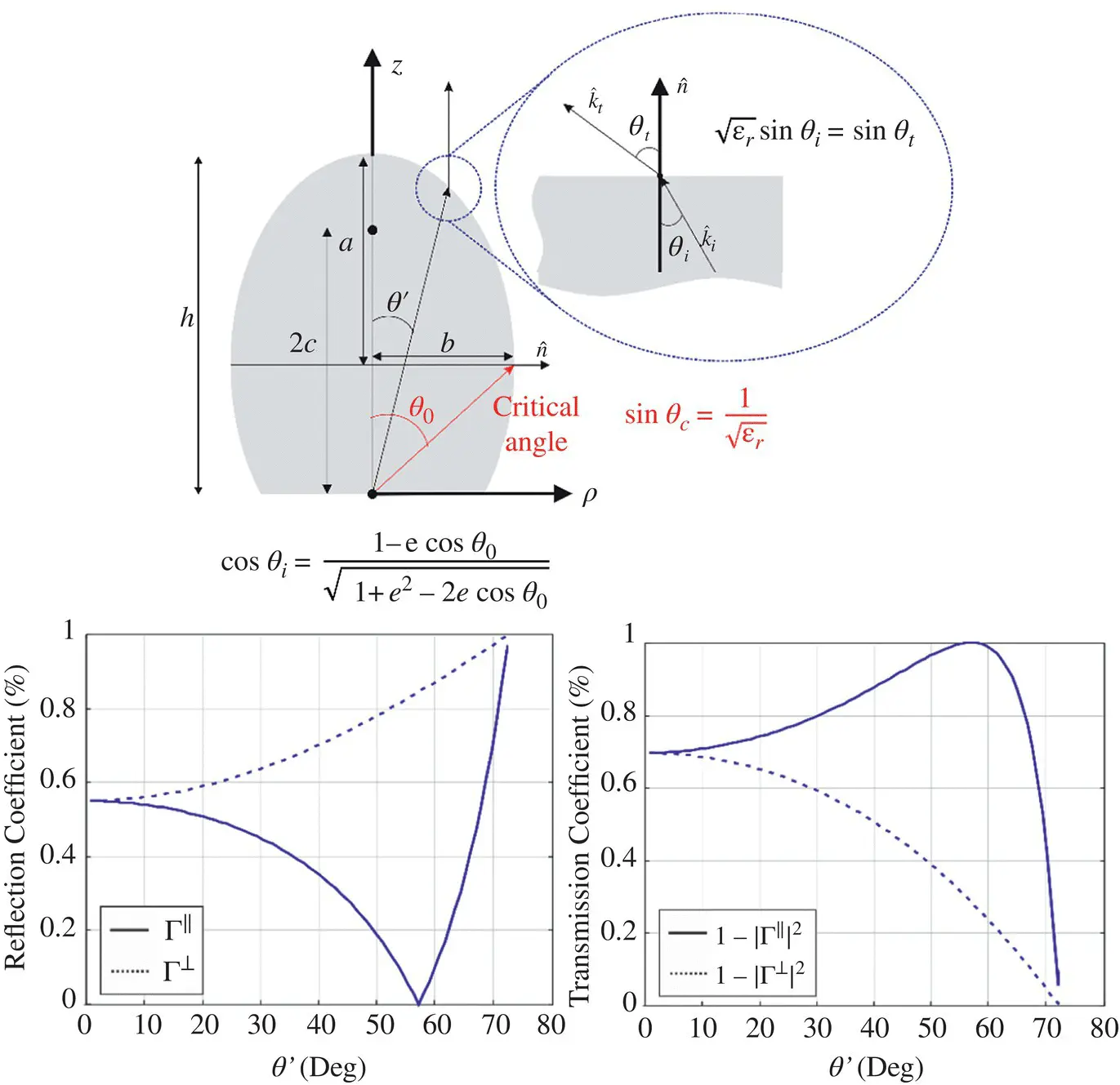
Figure 2.27(a) Reflection and (b) transmission coefficient for a silicon lens as a function of the angle. The reflection coefficient becomes 1 for angles larger or equal than the critical angle. The transmission coefficient becomes one for the Brewster angle.
E2.2
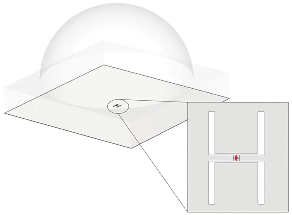
It is common to use an elliptical silicon lens antenna to be integrated with a high frequency detector. The detector, which operates at 350 GHz, it is placed on silicon ( ε r= 11.9). In order to couple the radiation into the detector an antenna consisting of two slots is used.
1 Give the length and separation of the slots in order to generate a field radiated inside an infinite silicon medium that could be used to illuminate efficiently the lens.
2 Design the lens dimensions such that its far field is characterized by a directivity of 30 dBs.
3 What are the sidelobe level, directivity, and reflection efficiency of lens antenna?
4 Assuming we aimed at the same directivity of the lens antenna, how would the two slot antenna and lens dimensions change if the dielectric material was εr = 4? What about the reflection efficiency?
Justify your answers with figures and try to give a physical insight into the problem.
E2.3
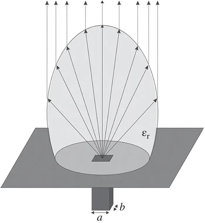
For automotive radar applications at 70 GHz, we need to design an elliptical lens antenna with a directivity of 30 dB fed by a rectangular waveguide as shown in the figure. The waveguide can be modeled considering the field in the aperture is approximated by the TE10 mode.
1 Make a study of the optimal dimensions of the waveguide and the lens to reach the specifications for the following different lens materials: materials: silicon (εr = 11.9), quartz (εr = 4) and plastic (εr = 2)
2 How does the change physical dimensions with the lens dielectric material?
3 How does the critical angle change with the lens dielectric material? And the directivity inside the dielectric and the reflection efficiency of the optimized waveguide feed?
4 How does the radiated patterns by the several lens antenna compared to each other?
Justify your answers with figures and try to give a physical insight into the problem.
References
1 1 Gulkis, S., Allen, M., Backus, C. et al. (2007). Remote sensing of a comet at millimeter and submillimeter wavelengths from an orbiting spacecraft. Planetary and Space Science 55 (9): 1050–1057.
2 2 Love, W. (1962). The diagonal horn antenna. Microwave Journal V: 117–122.
3 3 Johansson, J.F. and Whyborn, N.D. (1992). The diagonal horn as a sub‐millimeter wave antenna. IEEE Transactions on Microwave Theory and Techniques 40 (5): 795–800.
4 4 RPG Radiometer Physics GmbH https://radiometer‐physics.de
5 5 Day, P., Leduc, H., Goldin, A. et al. (2006). Antenna‐coupled microwave kinetic inductance detectors. Nuclear Instruments and Methods in Physics Research Section A: Accelerators, Spectrometers, Detectors and Associated Equipment 559 (2): 561–563.
6 6 Sarmah, N., Grzyb, J., Statnikov, K. et al. (2016). A fully integrated 240‐GHz direct‐conversion quadrature transmitter and receiver chipset in SiGe technology. IEEE Transactions on Microwave Theory and Techniques 64 (2): 562–574.
7 7 Skalare, A., van de Stadt, H., de Graauw, Th. et al. (1992). Double‐dipole antenna SIS receivers at 100 and 400 Gilz. Proceedings of the 3rd Mt. Conference Space Terahertz Technology, Ann Arbor, MI, 222–233.
8 8 Semenov, A.D., Hubers, H.‐W., Richter, H. et al. (2003). Superconducting hot‐electron bolometer mixer for terahertz heterodyne receivers. IEEE Transactions on Applied Superconductivity 13 (2): 168–171.
9 9 Kormanyos, B.K., Ostdiek, P.H., Bishop, W.L. et al. (1993). A planar wideband 80–200 GHz subharmonic receiver. IEEE Transactions on Microwave Theory and Techniques 41 (10): 1730–1737.
10 10 Garufo, A., Carluccio, G., Freeman, J.R. et al. (2018). Norton equivalent circuit for pulsed photoconductive antennas—part II: experimental validation. IEEE Transactions on Antennas and Propagation 66 (4): 1646–1659.
11 11 Garufo, A., Llombart, N., and Neto, A. (2016). Radiation of logarithmic spiral antennas in the presence of dense dielectric lenses. IEEE Transactions on Antennas and Propagation 64 (10): 4168–4177.
12 12 Chattopadhyay, G., Glenn, J., Bock, J.J. et al. (2003). Feed horn coupled bolometer arrays for SPIRE – design, simulations, and measurements. IEEE Transactions on Microwave Theory and Techniques 51 (10): 2139–2146.
13 13 Kangas, M.M., Ansmann, M., Horgan, B. et al. (2005). A 31 pixel flared 100‐GHz high‐gain scalar corrugated nonbonded platelet antenna array. IEEE Antennas and Wireless Propagation Letters 4: 245–248.
14 14 Leech, J., Tan, B.K., Yassin, G. et al. (2011). Multiple flare‐angle horn feeds for sub‐mm astronomy and cosmic microwave background experiments. Astronomy and Astrophysics 532: A61.
Читать дальшеИнтервал:
Закладка:
Похожие книги на «Fundamentals of Terahertz Devices and Applications»
Представляем Вашему вниманию похожие книги на «Fundamentals of Terahertz Devices and Applications» списком для выбора. Мы отобрали схожую по названию и смыслу литературу в надежде предоставить читателям больше вариантов отыскать новые, интересные, ещё непрочитанные произведения.


Обсуждение, отзывы о книге «Fundamentals of Terahertz Devices and Applications» и просто собственные мнения читателей. Оставьте ваши комментарии, напишите, что Вы думаете о произведении, его смысле или главных героях. Укажите что конкретно понравилось, а что нет, и почему Вы так считаете.