Fundamentals of Terahertz Devices and Applications
Здесь есть возможность читать онлайн «Fundamentals of Terahertz Devices and Applications» — ознакомительный отрывок электронной книги совершенно бесплатно, а после прочтения отрывка купить полную версию. В некоторых случаях можно слушать аудио, скачать через торрент в формате fb2 и присутствует краткое содержание. Жанр: unrecognised, на английском языке. Описание произведения, (предисловие) а так же отзывы посетителей доступны на портале библиотеки ЛибКат.
- Название:Fundamentals of Terahertz Devices and Applications
- Автор:
- Жанр:
- Год:неизвестен
- ISBN:нет данных
- Рейтинг книги:4 / 5. Голосов: 1
-
Избранное:Добавить в избранное
- Отзывы:
-
Ваша оценка:
Fundamentals of Terahertz Devices and Applications: краткое содержание, описание и аннотация
Предлагаем к чтению аннотацию, описание, краткое содержание или предисловие (зависит от того, что написал сам автор книги «Fundamentals of Terahertz Devices and Applications»). Если вы не нашли необходимую информацию о книге — напишите в комментариях, мы постараемся отыскать её.
Fundamentals of Terahertz Devices and Applications
Fundamentals of Terahertz Devices and Applications — читать онлайн ознакомительный отрывок
Ниже представлен текст книги, разбитый по страницам. Система сохранения места последней прочитанной страницы, позволяет с удобством читать онлайн бесплатно книгу «Fundamentals of Terahertz Devices and Applications», без необходимости каждый раз заново искать на чём Вы остановились. Поставьте закладку, и сможете в любой момент перейти на страницу, на которой закончили чтение.
Интервал:
Закладка:
In a LWA, the maximum directivity is directly proportional to the super‐layer permittivity but inversely proportional to the relative bandwidth. This resonant behavior is well known as the main drawback of LWA and limits their use to narrowband applications. However, this drawback can be partially solved when the leaky‐wave antenna is radiating in a semi‐infinity medium [25]. Indeed the use of a resonant air gap cavity for small antennas radiating into a dense medium ensures a highly directive beam with most of the energy being radiated for angles smaller than the air‐dielectric critical angle over bandwidths ranging from 10% to 40% depending on the lens material [45].
2.4.1 Analysis of the Leaky‐wave Propagation Constant
In this section, we will analyze the propagation constant, k ρlw, of the leaky waves propagating in the air cavity. For this evaluation the propagation constant, we will approximate the aperture field of Fabry–Perot leaky‐wave antennas as  and use the approximate analytical equations provided in [46]. The value of this propagation constant depends on the impedance, Z L, seen from the top of the half‐wavelength cavity in the equivalent transmission line model. For a dielectric quartz (being
  ) super‐layer with a quarter wavelength thickness, this impedance is
  . The pointing direction of the leaky‐wave modes is in this case 17°. If we need a more directive antenna, a lower Z Lis required in order to achieve less attenuated mode, implying stronger multiple‐reflections (i.e. more resonant), and thus, less bandwidth.
If instead of a dielectric super‐layer stratification we consider an infinite layer of silicon, the impedance seen on top of the cavity is  . Since
 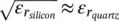 , the impedances associated with the quartz super‐layer and the infinite silicon layer are comparable and consequently, the leaky‐wave propagation constants. Figure 2.13shows the real and imaginary parts of the propagation constant for the three possible propagating modes: two TM and one TE . On the left axis of the figure, the propagation constants are normalized to the free space propagation constant k 0. The main mode TM 1and TE 1points towards approximately 18°, whereas the non‐desired mode TM 0radiates towards larger angles, i.e. 81°. However, if we calculate the pointing angles inside the dielectric, from the right axis of the figure, where the propagation constant is normalized to
  instead of k 0, we obtain values of about 6° for the main poles, which will translate into ε rtimes more directive pattern inside the dielectric medium without compromising the bandwidth.
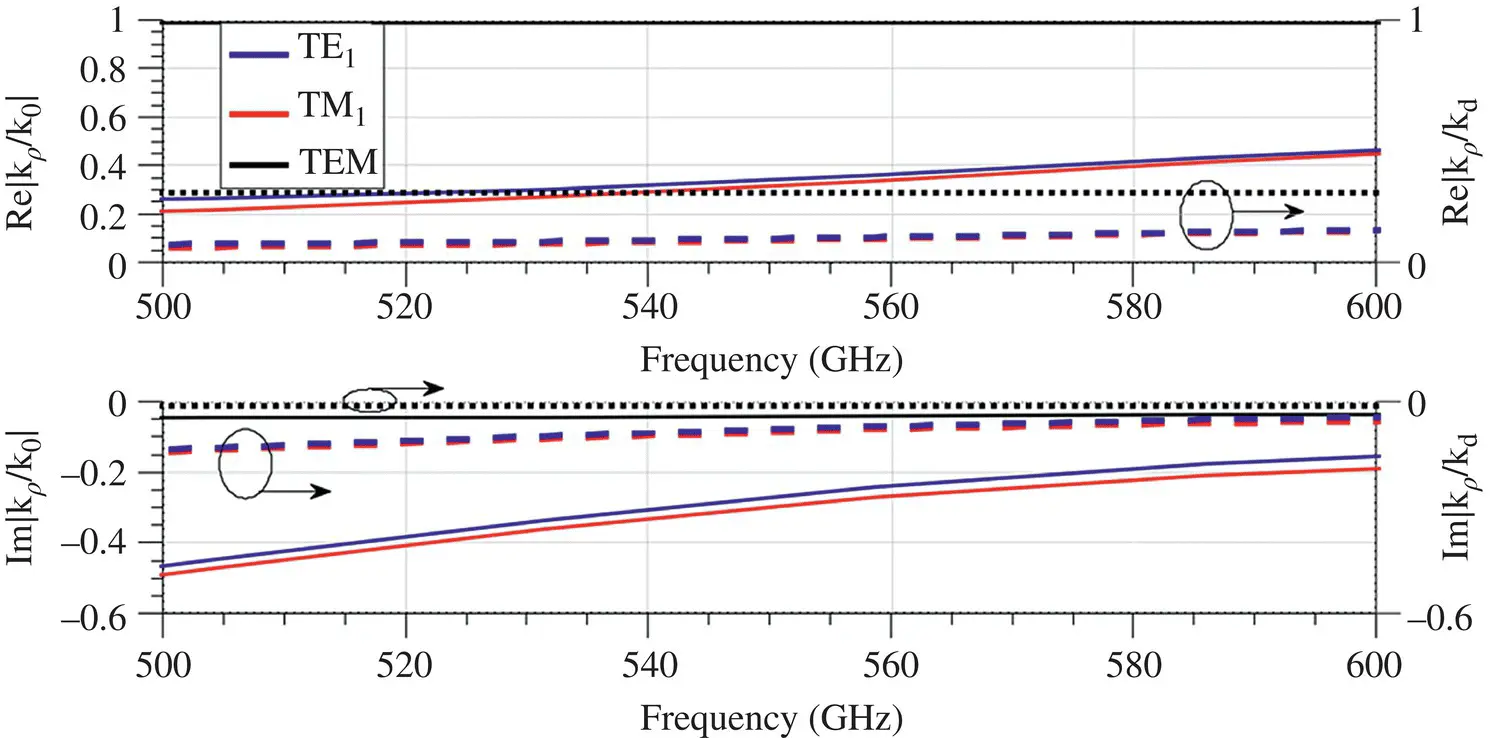
Figure 2.13Real and imaginary parts of the propagation constants k lwof the leaky‐wave modes present in an air cavity ( h = 275 μm) and infinite silicon dielectric medium. On the left axis, k lwis normalized to the free space propagation constant, k 0, whereas k lw(shown in the right axis) is normalized to the propagation constant in the dielectric,  .
.
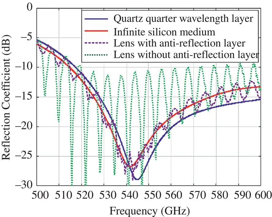
Figure 2.14Input reflection coefficient of a waveguide loaded with a double‐slot iris in the presence of an air cavity ( h = 275 μm) shown in [25]. The feed dimensions are: R in= 109.7 μm, α = 50° and wg = 367.6 μm. Several cases are considered on top of the cavity: a quartz quarter wavelength super‐layer (  ); an infinite silicon medium ( ε rs= 11.9); and an extended; hemispherical lens with R = 6 mm and L t/ R = 0.2 with and without a coating.
Source : Modified from Llombart et al. [25]; John Wiley & Sons.
Another advantage of this configuration is that the leaky‐wave mode shows the same frequency behavior as the quartz super‐layer, even if a more directive feed is radiated inside the dielectric, and therefore will have similar antenna impedances and bandwidth. Figure 2.14shows the simulated reflection coefficient using a full‐wave simulator of a square waveguide loaded by a double‐slot iris in the presence of the resonant air‐cavity. Several cases are shown in the figure, all of them with the same cavity and feed dimensions: an infinite silicon dielectric medium, a quartz quarter wavelength super‐layer, and a silicon lens on top of the cavity with and without coating. The infinite silicon medium and quartz quarter wavelength super‐layer present very similar reflection coefficients since they both present very similar cavity load impedances Z l. A comparison in the reflection coefficient with and without an anti‐reflection layer of ε r= 3.45 is shown in Figure 2.14. Note the strong effect of the multiple reflections on the reflection coefficient when an antireflective coating is not used.
All in all, when employing LWA, one should consider different dielectric combinations, e.g. infinite quartz layer, quartz cavity, and silicon lens, depending on the trade‐offs between the bandwidth and the directivity [45].
2.4.2 Primary Fields Radiated by a Leaky‐wave Antenna Feed on an Infinite Medium
This part will explain how to calculate the radiated fields into an infinite medium of a certain permittivity starting from a known aperture distribution. These fields can be then used as the incident fields in the previously explained lens analysis. We will use the example of a leaky‐wave feed over silicon but it can be applied to any source or lens dielectric material.
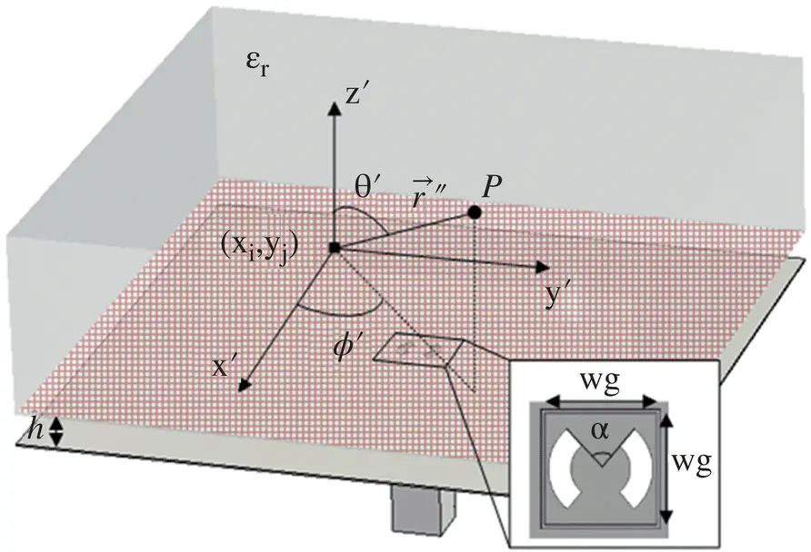
Figure 2.15Sketch of the leaky‐wave feed with its main parameters. The red grid represents the field aperture grid.
The basic geometry of the feed is shown in Figure 2.15. A waveguide exciting the fundamental mode mounted under an infinite ground plane with an iris. Above the iris, there is a resonant air cavity and a silicon slab that extends infinitely in z and the xy plane.
Читать дальшеИнтервал:
Закладка:
Похожие книги на «Fundamentals of Terahertz Devices and Applications»
Представляем Вашему вниманию похожие книги на «Fundamentals of Terahertz Devices and Applications» списком для выбора. Мы отобрали схожую по названию и смыслу литературу в надежде предоставить читателям больше вариантов отыскать новые, интересные, ещё непрочитанные произведения.


Обсуждение, отзывы о книге «Fundamentals of Terahertz Devices and Applications» и просто собственные мнения читателей. Оставьте ваши комментарии, напишите, что Вы думаете о произведении, его смысле или главных героях. Укажите что конкретно понравилось, а что нет, и почему Вы так считаете.