Fundamentals of Terahertz Devices and Applications
Здесь есть возможность читать онлайн «Fundamentals of Terahertz Devices and Applications» — ознакомительный отрывок электронной книги совершенно бесплатно, а после прочтения отрывка купить полную версию. В некоторых случаях можно слушать аудио, скачать через торрент в формате fb2 и присутствует краткое содержание. Жанр: unrecognised, на английском языке. Описание произведения, (предисловие) а так же отзывы посетителей доступны на портале библиотеки ЛибКат.
- Название:Fundamentals of Terahertz Devices and Applications
- Автор:
- Жанр:
- Год:неизвестен
- ISBN:нет данных
- Рейтинг книги:4 / 5. Голосов: 1
-
Избранное:Добавить в избранное
- Отзывы:
-
Ваша оценка:
Fundamentals of Terahertz Devices and Applications: краткое содержание, описание и аннотация
Предлагаем к чтению аннотацию, описание, краткое содержание или предисловие (зависит от того, что написал сам автор книги «Fundamentals of Terahertz Devices and Applications»). Если вы не нашли необходимую информацию о книге — напишите в комментариях, мы постараемся отыскать её.
Fundamentals of Terahertz Devices and Applications
Fundamentals of Terahertz Devices and Applications — читать онлайн ознакомительный отрывок
Ниже представлен текст книги, разбитый по страницам. Система сохранения места последней прочитанной страницы, позволяет с удобством читать онлайн бесплатно книгу «Fundamentals of Terahertz Devices and Applications», без необходимости каждый раз заново искать на чём Вы остановились. Поставьте закладку, и сможете в любой момент перейти на страницу, на которой закончили чтение.
Интервал:
Закладка:
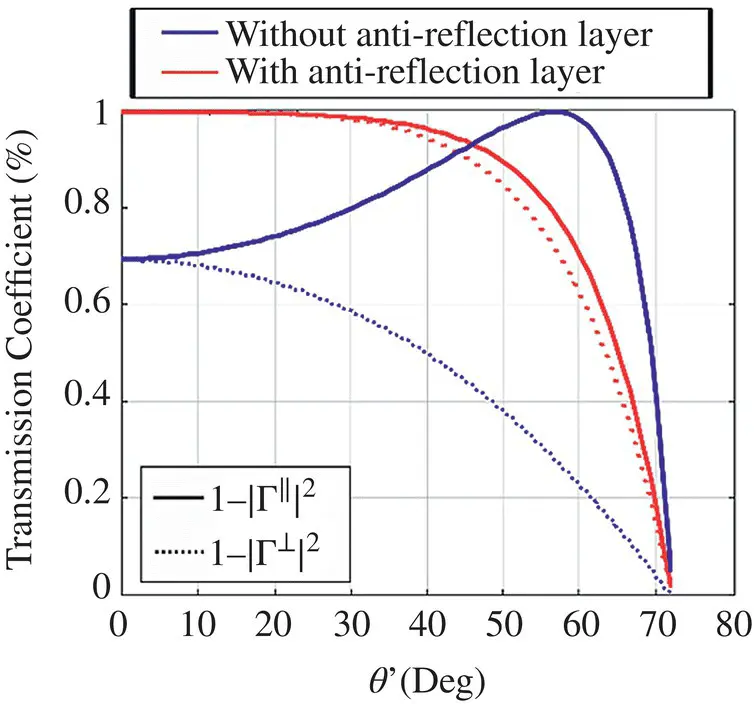
Figure 2.8Parallel and perpendicular transmission coefficient for a lens made in silicon with and without matching layer for a silicon lens ( ε r≈ 11.9).
Silicon is the dielectric material employed in integrated lenses and circuit substrates. It is an inherently strong and excellent material in terms of losses, due to its high resistivity (≥10 kΩ cm), which lowers the loss tangent to tan δ ≤ 10 −4. It has also a large thermal conductivity, meaning that for cryogenic applications it will absorb little of the incoming heat load and conduct it efficiently to the edge where the heat sinks are mounted. Moreover, thanks to its uniformity and homogeneity, it is a material well suited for polarization measurements. The high permittivity of silicon ( ε r≈ 11.9) allows designs with strong focusing and smaller thicknesses; however, it presents a major drawback in terms of reflection losses. At submillimeter‐wave frequencies, the plastic Parylene‐C is extensively used as an antireflective layer thanks to the close match to the ideal index and its deposition through pyrolysis [35]. Other plastics such as Cirlex have suitable permittivity, but they are glued to the silicon with lossy epoxy adhesive [36]. Other methods include the synthesis of artificial dielectric coatings through the patterning of subwavelength grooves through micro‐machining processes [37]. This artificial dielectric coating can synthesize the desired permittivity and behave as a continuous medium providing the closest match to the ideal antireflective coating.
2.3 Extended Semi‐hemispherical Lens Antennas
While elliptical lenses reach the highest possible directivity, extended hemispherical lenses are often employed to ease their fabrication. This alternative configuration can have a close performance to the elliptical when the primary feed is designed in such a way to excite only the upper part of the dielectric lens and a dense material is used. The dimensions of the lens are chosen to approximate the focusing properties of the elliptical lens when the feed is placed at the foci. The synthesis of the ellipse is achieved using a semi‐hemisphere of unit radius defined as:
(2.55) 
and an extension defined by L (see Fig. 2.9). The distance b + c should be equal to L + 1 so both lenses are overlaid. Thus, the extension height L can be defined as:
(2.56) 
It can also be synthesized the other way around, from an extended semi‐hemispherical lens defined with the R and L , we can obtain the equivalent ellipse with the following expressions:
(2.57) 
Figure 2.9Synthesis of an elliptical lens from an extended hemispherical lens for silicon, fused silica and PTFE. Note that the extended hemisphere is a good approximation of the elliptical lens at high dielectric constants.
(2.58) 
(2.59) 
Depending on the dielectric constant, the fitting of the elliptical lens and the extended hemispherical lens varies. Three examples are shown in Figure 2.9where both lenses of silicon ( ε r≈ 11.9), quartz ( ε r≈ 4.5) and polytetrafluoroethylene (PTFE) ( ε r≈ 2). The rays from a broadside plane wave incident onto the extended semi‐hemispherical lens, as opposed to the elliptical lens, do not come to a point focus, thus, which means that the lens introduces an aberration to the radiated fields. But as we will see in the following sections, even if it does not couple well to a planar equi‐phase front, the extended hemispherical lens will couple well to a Gaussian‐beam system.
2.3.1 Radiation of Extended Semi‐hemispherical Lenses
In Section 2.2, we computed the radiation pattern from an elliptical lens antenna by deriving the currents on a planar aperture above the lens and, from them, we obtained the radiated fields from the lens antenna. In this section, we will explain how to compute the radiated fields of the extended hemispherical lens antenna from the currents evaluated on the lens surface. A PO method provides an approximation of these surface currents over a lens of several wavelengths. Using again the Love's Equivalence Principle, the radiated fields from the antenna feed obtained previously are used to compute the equivalent magnetic and electric sheet currents outside of the lens surface:
(2.60) 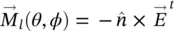
(2.61) 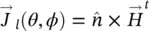
where  is the normal vector to the surface of the lens ( Figure 2.10) and
  and
and  are the radiated fields from the antenna feed transferred outside the boundary of the lens. The transmitted fields can be calculated similarly that how it was done for the elliptical lens. The PO assumes that the equivalent currents can be formulated directly using the transmitted fields. Those are computed by approximating the lens surface locally by a flat dielectric‐air interface and using the Fresnel transmission coefficients for plane waves as explained previously. Thus, the radiated field from the feed is decomposed into their parallel and perpendicular components to the incidence plane (see Figure 2.10) and multiplied by the corresponding transmission coefficient. The total field is defined by
 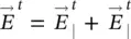 , and the total magnetic field can be equivalently calculated as
 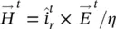 . Each of the components is given by:
Интервал:
Закладка:
Похожие книги на «Fundamentals of Terahertz Devices and Applications»
Представляем Вашему вниманию похожие книги на «Fundamentals of Terahertz Devices and Applications» списком для выбора. Мы отобрали схожую по названию и смыслу литературу в надежде предоставить читателям больше вариантов отыскать новые, интересные, ещё непрочитанные произведения.


Обсуждение, отзывы о книге «Fundamentals of Terahertz Devices and Applications» и просто собственные мнения читателей. Оставьте ваши комментарии, напишите, что Вы думаете о произведении, его смысле или главных героях. Укажите что конкретно понравилось, а что нет, и почему Вы так считаете.