Fundamentals of Terahertz Devices and Applications
Здесь есть возможность читать онлайн «Fundamentals of Terahertz Devices and Applications» — ознакомительный отрывок электронной книги совершенно бесплатно, а после прочтения отрывка купить полную версию. В некоторых случаях можно слушать аудио, скачать через торрент в формате fb2 и присутствует краткое содержание. Жанр: unrecognised, на английском языке. Описание произведения, (предисловие) а так же отзывы посетителей доступны на портале библиотеки ЛибКат.
- Название:Fundamentals of Terahertz Devices and Applications
- Автор:
- Жанр:
- Год:неизвестен
- ISBN:нет данных
- Рейтинг книги:4 / 5. Голосов: 1
-
Избранное:Добавить в избранное
- Отзывы:
-
Ваша оценка:
Fundamentals of Terahertz Devices and Applications: краткое содержание, описание и аннотация
Предлагаем к чтению аннотацию, описание, краткое содержание или предисловие (зависит от того, что написал сам автор книги «Fundamentals of Terahertz Devices and Applications»). Если вы не нашли необходимую информацию о книге — напишите в комментариях, мы постараемся отыскать её.
Fundamentals of Terahertz Devices and Applications
Fundamentals of Terahertz Devices and Applications — читать онлайн ознакомительный отрывок
Ниже представлен текст книги, разбитый по страницам. Система сохранения места последней прочитанной страницы, позволяет с удобством читать онлайн бесплатно книгу «Fundamentals of Terahertz Devices and Applications», без необходимости каждый раз заново искать на чём Вы остановились. Поставьте закладку, и сможете в любой момент перейти на страницу, на которой закончили чтение.
Интервал:
Закладка:
(2.17) 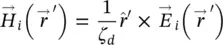
where  is the medium wave impedance. The reference system used to evaluate this field is taken at the lower focus of the elliptical lens.
Next, we will use these approximations to express the radiation in the far‐field of the elliptical lens, when illuminated from this incident field  .
.
2.2.2.1 Transmission Function 
Let's now analyze an arbitrary point Q over a lens surface. The transmitted magnetic and electric field outside of the lens  are related to the incident field
  through the transmission function
  as given in (2.17). In general, at each point Q , the incident field can be decomposed into parallel‐TM
  and perpendicular‐TE
  components:
(2.18) 
where  and
and  are the parallel and perpendicular polarization vectors (see Figure 2.3b), and can be expressed in spherical coordinates for the on‐focus feed as:
(2.19) 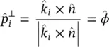
(2.20) 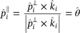
which brings to:
(2.21) 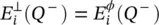
(2.22) 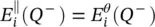
For a feed placed in the center of the coordinate system, the propagation vector see Figure 2.3b inside and outside of the lens are defined as:
(2.23) 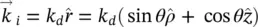
(2.24) 
The normal vector to the lens surface defined in cylindrical coordinates for an elliptical lens is:
(2.25) 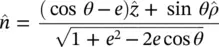
Then, the transmitted field can be expressed as:
(2.26) 
being τ ⊥( Q ), τ ∥( Q ) the Fresnel transmission coefficients which are evaluated assuming a locally flat boundary (see Figure 2.4):
(2.27) 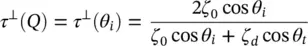
(2.28) 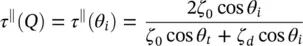
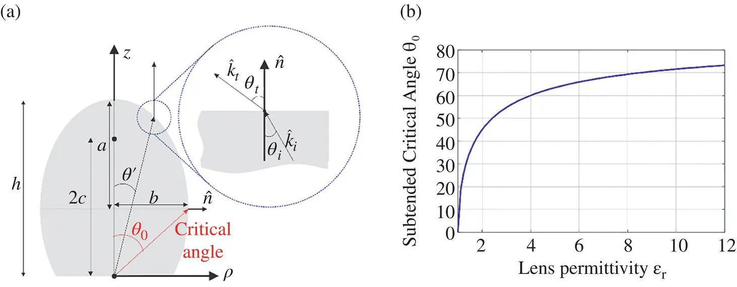
Figure 2.4(a) Scheme of the critical angle calculation on an elliptical lens. (b) Subtended critical angle vs permittivity of the elliptical lens.
where 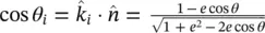 . Using (2.27)and (2.28)in the equation (2.26), and considering that
  and
and 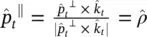 , we finally arrive at the expression of the transmitted fields at the equivalent aperture:
(2.29) 
(2.30) 
The spatial domain of ( 2.29and 2.30) is determined by the GO approximation. In case of a full angular lens as depicted in Figure 2.4a, the GO transmitted fields will be zero after the critical angle. For a flat interface between a dense medium and free space, the angle of refraction θ tincreases as the incident angle θ iincreases ( θ t> θ i). Total internal reflection ( Γ = 1) occurs when the angle of refraction is 90° and the incident angle is known as the critical angle 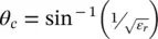 . After this angle there is no transmission, and therefore, this angle defines the domain of the equivalent aperture. As this angle lies at the center distance between the two focuses, the radius of the equivalent aperture is therefore the minor axis b . Thus, the fields in ( 2.29and 2.30) are zero for a region outside the lens antenna aperture, i.e. ρ > D /2 with D = 2 b in the case of a full angular lens. In the case of a smaller angular lens such as in [33], the spatial domain of the fields will be given by edge angle of the lens instead. Using the definition of the critical angle and that of the normal vector,
  , we can evaluate the subtended critical angle, θ 0, seen from the lens feeder in Figure 2.4a at the critical angle:
Интервал:
Закладка:
Похожие книги на «Fundamentals of Terahertz Devices and Applications»
Представляем Вашему вниманию похожие книги на «Fundamentals of Terahertz Devices and Applications» списком для выбора. Мы отобрали схожую по названию и смыслу литературу в надежде предоставить читателям больше вариантов отыскать новые, интересные, ещё непрочитанные произведения.


Обсуждение, отзывы о книге «Fundamentals of Terahertz Devices and Applications» и просто собственные мнения читателей. Оставьте ваши комментарии, напишите, что Вы думаете о произведении, его смысле или главных героях. Укажите что конкретно понравилось, а что нет, и почему Вы так считаете.