Fundamentals of Terahertz Devices and Applications
Здесь есть возможность читать онлайн «Fundamentals of Terahertz Devices and Applications» — ознакомительный отрывок электронной книги совершенно бесплатно, а после прочтения отрывка купить полную версию. В некоторых случаях можно слушать аудио, скачать через торрент в формате fb2 и присутствует краткое содержание. Жанр: unrecognised, на английском языке. Описание произведения, (предисловие) а так же отзывы посетителей доступны на портале библиотеки ЛибКат.
- Название:Fundamentals of Terahertz Devices and Applications
- Автор:
- Жанр:
- Год:неизвестен
- ISBN:нет данных
- Рейтинг книги:4 / 5. Голосов: 1
-
Избранное:Добавить в избранное
- Отзывы:
-
Ваша оценка:
Fundamentals of Terahertz Devices and Applications: краткое содержание, описание и аннотация
Предлагаем к чтению аннотацию, описание, краткое содержание или предисловие (зависит от того, что написал сам автор книги «Fundamentals of Terahertz Devices and Applications»). Если вы не нашли необходимую информацию о книге — напишите в комментариях, мы постараемся отыскать её.
Fundamentals of Terahertz Devices and Applications
Fundamentals of Terahertz Devices and Applications — читать онлайн ознакомительный отрывок
Ниже представлен текст книги, разбитый по страницам. Система сохранения места последней прочитанной страницы, позволяет с удобством читать онлайн бесплатно книгу «Fundamentals of Terahertz Devices and Applications», без необходимости каждый раз заново искать на чём Вы остановились. Поставьте закладку, и сможете в любой момент перейти на страницу, на которой закончили чтение.
Интервал:
Закладка:
2.2.2.3 Equivalent Current Distribution and Far‐field Calculation
The equivalent current distributions on the aperture, using the incident field is defined as in ( 2.21and 2.22) and the phase relation derived in (2.1), can then be written as follows:
(2.50) 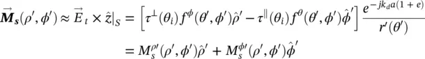
(2.51) 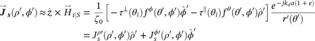
where r ′ ( θ ′) is given by (2.5)and tan θ ′ = ρ ′/ z ′ where 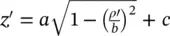 . The vectorial components of these equivalent current distributions can be also expressed in Cartesian coordinates using
  and
and  .
.
With these equations, we have determined the surface currents on the lens aperture, and thus, the far field patterns in the reference system used in Figure 2.6can be obtained using the following expressions:
(2.52) 
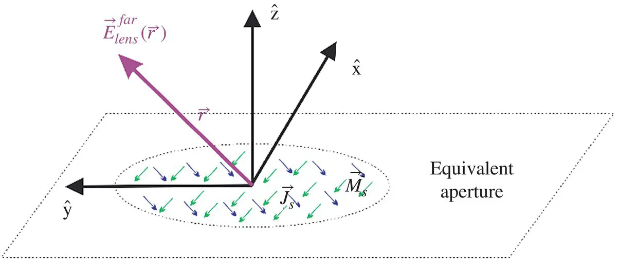
Figure 2.6Reference system for the evaluation of the far fields radiated by the elliptical lens antenna.
(2.53) 
where  and
and  ; and η 0is the intrinsic impedance of free space.
2.2.2.4 Lens Reflection Efficiency
One of the main differences of lenses w.r.t. reflectors is the fact that in a reflector all the incident field is transformed into a transmitted field as the surface can be modeled as a perfect electric conductor (PEC). However, in the case of lenses, the radiation principle is based on the refraction law; thus some incident energy is transmitted to the air but some part is reflected inside of the lens toward the top focus (see Figure 2.7a) [34]. GO/PO field approximation only includes the effect in the far field of the first transmitted rays. Part of the energy is actually reflected in the lens interface. This energy will eventually be radiated to the far field via multiple reflections or it will be lost in the lens material. In the GO/PO field analysis, this reflected energy is simply considered a loss in efficiency. That is typically a good assumption since the multiple reflections do not usually contribute to the radiated field main beam, as they have a random phase, but to the far side‐lobes. It means that the broadside gain of the antenna can be related as the directivity multiply by the radiation efficiency:
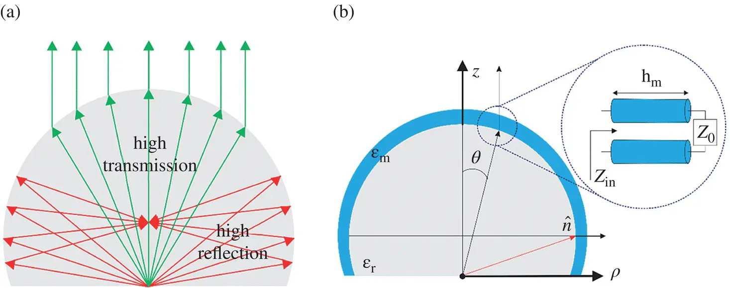
Figure 2.7(a) High transmission and high reflection region of a silicon made elliptical lens. (b) Elliptical lens with a matching layer and its equivalent transmission line representation.
(2.54) 
where the radiation efficiency, η r, is the ratio between the power radiated by the lens into the air and the power radiated by the primary source inside the lens  .
.
The amount of energy reflected inside the lens depends on how the lens feed illuminates the lens surface (see Figure 2.7b). We can identify two distinct zones as shown in Figure 2.7a. The top part of the lens is where the energy transmission is the highest, and therefore the most efficient part, whereas the lateral part leads to high reflected energy (even total at the critical angle) and therefore is the least efficient one [34]. That is why the lens feed should be designed to illuminate only the top part of the lens.
In order to improve the reflection efficiency of lens antennas, we can use a quarter wavelength impedance transformers. This impedance transformer is typically designed for broadside radiation (top part of the lens). It can be easily analyzed using a transmission line model for the TE and TM polarizations (corresponding to orthogonal and parallel polarizations, respectively), with the characteristic impedances of the lines representing the different mediums indicated with i defined as 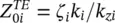 and
and 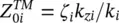 with
with 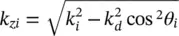 as shown in Figure 2.7b. Using this model, we can derive the condition for no reflection when Z in= ζ dwhich implies that the permittivity of the antireflective layer material is
  and its thickness
  .
.
The reflections coefficients of a silicon elliptical lens with and without anti‐reflection layer are shown in Figure 2.8as a function of the lens feeder angle (as in Figure 2.4a). Total internal reflection ( Γ = 1) occurs when the incident angle onto the lens surface is 90° corresponding to about 72° for the feed angle. Before that angle, there is a total transmission angle for the parallel polarization at the called Brewster's angle. The same figure shows the improved transmission coefficient of a lens made in silicon with an antireflective layer compared to the same lens without the antireflective layer. As it is shown, the transmission coefficient remains high until up 40° approximately with the use of an antireflective layer, and the parallel and perpendicular coefficients have now comparable values and therefore they will not introduce asymmetries in the azimuthal angle. It is important to mention that the introduction of an antireflective layer in lenses does not remove the problem of the critical angle. In both cases, the energy transmitted goes to zero at about 72°.
Читать дальшеИнтервал:
Закладка:
Похожие книги на «Fundamentals of Terahertz Devices and Applications»
Представляем Вашему вниманию похожие книги на «Fundamentals of Terahertz Devices and Applications» списком для выбора. Мы отобрали схожую по названию и смыслу литературу в надежде предоставить читателям больше вариантов отыскать новые, интересные, ещё непрочитанные произведения.


Обсуждение, отзывы о книге «Fundamentals of Terahertz Devices and Applications» и просто собственные мнения читателей. Оставьте ваши комментарии, напишите, что Вы думаете о произведении, его смысле или главных героях. Укажите что конкретно понравилось, а что нет, и почему Вы так считаете.