Fundamentals of Terahertz Devices and Applications
Здесь есть возможность читать онлайн «Fundamentals of Terahertz Devices and Applications» — ознакомительный отрывок электронной книги совершенно бесплатно, а после прочтения отрывка купить полную версию. В некоторых случаях можно слушать аудио, скачать через торрент в формате fb2 и присутствует краткое содержание. Жанр: unrecognised, на английском языке. Описание произведения, (предисловие) а так же отзывы посетителей доступны на портале библиотеки ЛибКат.
- Название:Fundamentals of Terahertz Devices and Applications
- Автор:
- Жанр:
- Год:неизвестен
- ISBN:нет данных
- Рейтинг книги:4 / 5. Голосов: 1
-
Избранное:Добавить в избранное
- Отзывы:
-
Ваша оценка:
Fundamentals of Terahertz Devices and Applications: краткое содержание, описание и аннотация
Предлагаем к чтению аннотацию, описание, краткое содержание или предисловие (зависит от того, что написал сам автор книги «Fundamentals of Terahertz Devices and Applications»). Если вы не нашли необходимую информацию о книге — напишите в комментариях, мы постараемся отыскать её.
Fundamentals of Terahertz Devices and Applications
Fundamentals of Terahertz Devices and Applications — читать онлайн ознакомительный отрывок
Ниже представлен текст книги, разбитый по страницам. Система сохранения места последней прочитанной страницы, позволяет с удобством читать онлайн бесплатно книгу «Fundamentals of Terahertz Devices and Applications», без необходимости каждый раз заново искать на чём Вы остановились. Поставьте закладку, и сможете в любой момент перейти на страницу, на которой закончили чтение.
Интервал:
Закладка:
(2.31) 
As an example, Figure 2.4b shows θ 0as a function of the relative permittivity of the elliptical lens. It can be observed how the lower the permittivity, the smaller the angle is, and therefore, a more directive feed will be required to efficiently illuminate the lens above the critical angle.
2.2.2.2 Spreading Factor S ( Q )
Let's now analyze the power balance in an elliptical lens antenna. We can evaluate the incident power crossing an area A (see Figure 2.5a) by considering each ray incident on a point Q as a plane wave. The orthogonal and parallel components of the incident power are defined as follows:
(2.32) 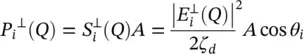
(2.33) 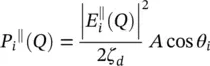
where S irepresents the amplitude of the Poynting vector. The same can be done for the reflected power towards inside of the lens:
(2.34) 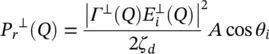
(2.35) 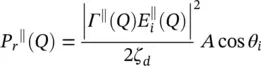
and for the transmitted power:
(2.36) 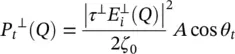
(2.37) 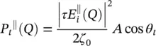
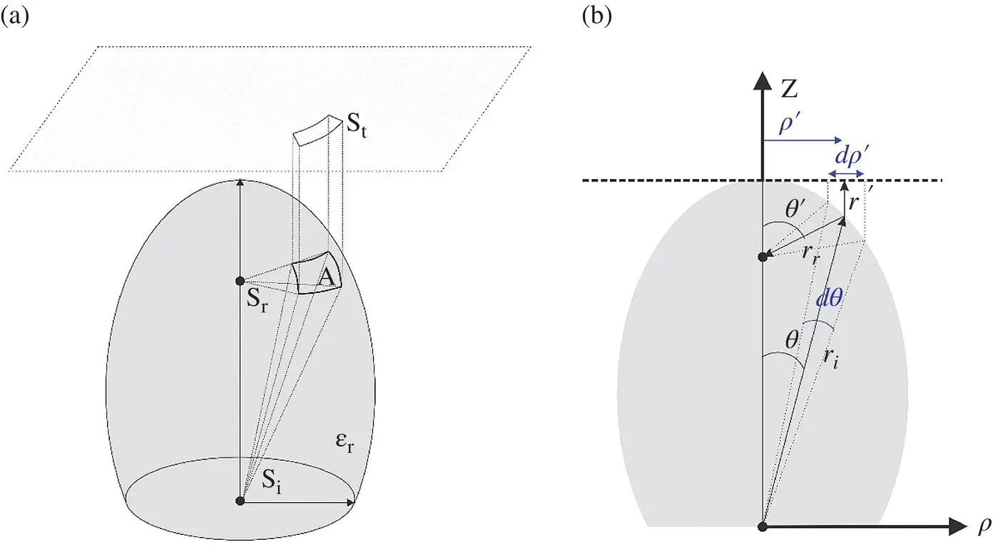
Figure 2.5(a) Incident, reflected, and transmitted power density in a dielectric lens. (b) Referenced geometrical parameters.
The relation between the incident, reflected and the transmitted power density is represented in Figure 2.5a. The power transmitted by the ellipse Pa and propagating in parallel to the z ‐axis through the aperture area of dA a= ρ ′ dρ ′ dϕ , is equal to the transmitted power, P t, by the ellipse through the area  ; where r iis the distances between the first focus and the lens surface (see Figure 2.5b). Moreover, the transmitted power is related to the power incident, on the lens surface, P i(i.e. neglecting the reflected power):
(2.38) 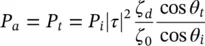
where P a= S a dA aand P i= S i dA i; S aand S iare the amplitude of the Poynting vectors of the aperture, and incident fields, respectively. Moreover, τ is the Fresnel coefficient in transmission, θ iand θ tare the incident and transmitted angles on the lens surface, respectively. By using the relations ρ ′ = r isin θ , (2.38)can be simplified as:
(2.39) 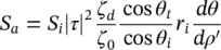
The amplitude of the aperture and incident Poynting vectors can be expressed as:
(2.40) 
(2.41) 
where | E a| is the amplitude of the electric field on the equivalent aperture of the lens, and | E i| is the amplitude of the far‐field pattern of the incident electric field. Moreover, the term  can be simplified as:
(2.42) 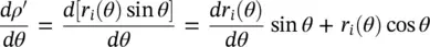
where 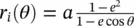 . The term
  can be calculated as:
(2.43) 
by substituting (2.43)in (2.42):
(2.44) 
by substituting in (2.39):
(2.45) 
For an elliptical lens with  , one can represent cos θ iand cos θ tas:
(2.46) 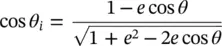
(2.47) 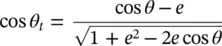
by substituting (2.46)and (2.47)in (2.45), the amplitude of the field at equivalent aperture of the lens is related to the amplitude of the incident field as:
(2.48) 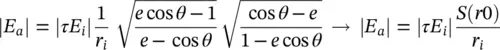
Therefore, the spreading factor can be defined as:
(2.49) 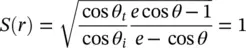
This is because, in the considered geometry (feed at the focus), the output GO phase front is planar and consequently has no power spreading.
Читать дальшеИнтервал:
Закладка:
Похожие книги на «Fundamentals of Terahertz Devices and Applications»
Представляем Вашему вниманию похожие книги на «Fundamentals of Terahertz Devices and Applications» списком для выбора. Мы отобрали схожую по названию и смыслу литературу в надежде предоставить читателям больше вариантов отыскать новые, интересные, ещё непрочитанные произведения.


Обсуждение, отзывы о книге «Fundamentals of Terahertz Devices and Applications» и просто собственные мнения читателей. Оставьте ваши комментарии, напишите, что Вы думаете о произведении, его смысле или главных героях. Укажите что конкретно понравилось, а что нет, и почему Вы так считаете.