Ralph Grabowski - AutoCAD For Dummies
Здесь есть возможность читать онлайн «Ralph Grabowski - AutoCAD For Dummies» — ознакомительный отрывок электронной книги совершенно бесплатно, а после прочтения отрывка купить полную версию. В некоторых случаях можно слушать аудио, скачать через торрент в формате fb2 и присутствует краткое содержание. Жанр: unrecognised, на английском языке. Описание произведения, (предисловие) а так же отзывы посетителей доступны на портале библиотеки ЛибКат.

- Название:AutoCAD For Dummies
- Автор:
- Жанр:
- Год:неизвестен
- ISBN:нет данных
- Рейтинг книги:5 / 5. Голосов: 1
-
Избранное:Добавить в избранное
- Отзывы:
-
Ваша оценка:
AutoCAD For Dummies: краткое содержание, описание и аннотация
Предлагаем к чтению аннотацию, описание, краткое содержание или предисловие (зависит от того, что написал сам автор книги «AutoCAD For Dummies»). Если вы не нашли необходимую информацию о книге — напишите в комментариях, мы постараемся отыскать её.
AutoCAD For Dummies
AutoCAD For Dummies
AutoCAD For Dummies — читать онлайн ознакомительный отрывок
Ниже представлен текст книги, разбитый по страницам. Система сохранения места последней прочитанной страницы, позволяет с удобством читать онлайн бесплатно книгу «AutoCAD For Dummies», без необходимости каждый раз заново искать на чём Вы остановились. Поставьте закладку, и сможете в любой момент перейти на страницу, на которой закончили чтение.
Интервал:
Закладка:
The Line command draws continuous lines. Real-world drawings include several different looks of lines, such as hidden, center, and section. Chapter 9covers how to apply these and several other properties to lines.
Follow these steps to use the Line command:
1 Start the Line command by clicking the Line button on the Draw panel on the Ribbon, or by entering L and then pressing Enter.
2 Draw line segments by picking several random points.
3 Terminate the command by pressing Enter, Esc, or the spacebar.
4 Press Enter or the spacebar to repeat the Line command. In AutoCAD, pressing Enter or the spacebar when no command is underway always repeats the last command.
5 Draw more line segments to complete the figure.If you need to undo some line segments, enter U and press Enter.
6 Enter C and press Enter to close the figure, which draws one more segment back to the first point you picked.The Close option doesn’t appear until you've created the first two line segments. You can’t close a single line.
 Pressing Enter or the spacebar whenever AutoCAD asks for a first point automatically selects the last point you picked, regardless of the previous or current command.
Connecting the lines with polyline
Drawing polylines composed of straight segments is much like drawing with the Line command, as shown in the steps in this section. The PLine command has a lot more options, however, so watch the prompts. If the Dynamic Input feature is on, press the down-arrow key to see the options listed near the cursor, or right-click to display the PLine right-click menu, or simply read the command line.
To draw a polyline composed of straight segments, follow these steps:
1 Click the Polyline button on the Draw panel of the Ribbon, or type PL at the command line and press Enter.AutoCAD starts the PLine command and prompts you to specify a start point.
2 Specify the starting point by clicking a point or typing coordinates.Now you truly do need to read the command line, because the Dynamic Input tooltip at the cursor doesn’t display any of the options. You can right-click or press the down-arrow key to see a list of the options at the cursor, as shown in Figure 6-2, but it’s usually faster to use the command line.AutoCAD displays the current polyline segment line width at the command line and prompts you to specify the other endpoint of the first polyline segment:Current line-width is 0.0000Specify next point or [Arc Halfwidth Length Undo Width]:
3 If the current line width isn’t zero, you can change it to zero by typing W to select the Width option and then entering 0 as the starting and ending widths, as shown in this command-line sequence: Specify next point or [Arc Halfwidth Length Undo Width]: WSpecify starting width <0.0000>: 0Specify ending width <0.0000>: 0Specify next point or [Arc Halfwidth Length Undo Width]: Despite what you may think, a zero-width polyline segment isn’t the AutoCAD equivalent of drawing with invisible ink. Zero width means, “Display this segment using the normal, single-pixel width on the screen, and print as thin as possible.” How can you tell when your pen has run out of invisible ink? You can see the writing.
4 Specify additional points by clicking or typing.After you specify the second point, AutoCAD adds the Close option to the prompt. The command line showsSpecify next point or [Arc Close Halfwidth Length Undo Width]: What you do next can get a little weird. If you invoke the Close option after selecting only the first and second points, PLine doubles back on itself and creates the second segment back over the first, unlike the Line command, which won’t. Normal practice would be to not invoke Close until you have created at least two non-collinear segments.
5 Pick several points to create several line segments, and then enter W to start the Width option. Then set a new width, as shown in this command line sequence: Starting width <0.0000>: 5Specify ending width <5.0000>: Press Enter
6 Pick several more points and note the line width of the new segments.
7 Set the Width option again: Starting width <5.0000>: 15Specify ending width <0.0000>: 0
8 Pick another point.You just created a cool arrowhead! Any time AutoCAD prompts for a length or distance, you can either type a value or you can show it what you want by picking two points in the drawing.
9 After you finish drawing segments, press Enter to leave the figure open, or type C and press Enter to close it back to the start.AutoCAD draws the final segment and miters all the corners perfectly.
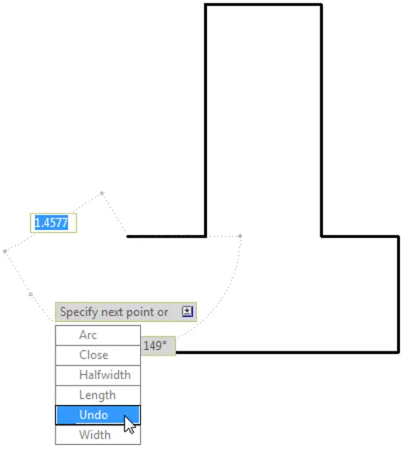
FIGURE 6-2:The optional extras.
 After you create a polyline, you can adjust its segments by grip-editing any of the vertex points. See Chapter 11for details on grip editing.
In the following steps, I spice things up by adding an arc segment to a polyline.
ALTERNATIVES TO THE LINE AND PLINE COMMANDS
The Line and PLine commands work well for drawing a series of end-to-end single lines, but you may want to draw a series of double lines to represent, for example, the edges of a wall or roadway. Here are some options:
Use the AutoCAD MLine command to draw multilines, which are a series of two or more parallel straight lines. The AutoCAD Multiline feature was full of limitations when it debuted way back in 1994 (in the notorious Release 13), and despite minor tweaks in AutoCAD 2006, it hasn’t improved significantly since then. It exists mostly for compatibility with MicroStation files. Look up the MLine and MLStyle commands in the AutoCAD online help system if you want to tangle with this feature, but be prepared to spend time experimenting, struggling, and (possibly) cursing. Don’t let small children near you.
Use the PLine command to draw a single set of connected line or arc segments or both, and then use the OFFset command (described in Chapter 11) to create one or more sets of parallel segments.
In AutoCAD LT only, use the DLine, or Double Line, command to draw pairs of parallel line or arc segments or both. Unlike MLine, DLine works well. AutoCAD LT doesn’t have the MLine command, which is more of a blessing than a limitation. AutoCAD, on the other hand, doesn’t have the DLine command. (Score one for the little brother!)
 Curved segments in polylines are circular arcs that you can create while running the PLine command. AutoCAD can draw other kinds of curves, including ellipses and splines, but not in the PLine command.
To draw a polyline that includes curved segments, follow these steps:
1 Repeat Steps 1–4 in the preceding step list.
2 To add one or more arc segments, type A, and then press Enter to select the Arc option.The prompt changes to show options for drawing arc segments. Most of these options correspond to the many ways of drawing circular arcs in AutoCAD; see the section on arcs in Chapter 7. The command line shows:Specify endpoint of arc or [Angle CEnter/CLose Direction Halfwidth Line Radius Second pt Undo Width]:
3 Specify the endpoint of the arc by clicking a point or typing coordinates.AutoCAD draws the curved segment of the polyline. The prompts continue to show arc segment options.Specify endpoint of arc or [Angle CEnter/CLose Direction Halfwidth Line Radius Second pt Undo Width]:The options at this point are toSpecify additional points to draw more arc segments.Choose another arc-drawing method, such as CEnter or Second point.Return to drawing straight-line segments with the Line option.In this example, you draw straight-line segments. Perhaps the most useful of the alternative arc-drawing methods is Second pt. It gives you more control over the direction of the arc but at the cost of losing tangency of adjacent segments. (Sometimes, it’s best not to go off on a tangent, anyway.) If you want both ends of the arc segments to be tangent to the adjacent line segments, draw the polyline as straight-line segments and then use the Fillet command (described in Chapter 11) to add the arcs later.
Читать дальшеИнтервал:
Закладка:
Похожие книги на «AutoCAD For Dummies»
Представляем Вашему вниманию похожие книги на «AutoCAD For Dummies» списком для выбора. Мы отобрали схожую по названию и смыслу литературу в надежде предоставить читателям больше вариантов отыскать новые, интересные, ещё непрочитанные произведения.


Обсуждение, отзывы о книге «AutoCAD For Dummies» и просто собственные мнения читателей. Оставьте ваши комментарии, напишите, что Вы думаете о произведении, его смысле или главных героях. Укажите что конкретно понравилось, а что нет, и почему Вы так считаете.