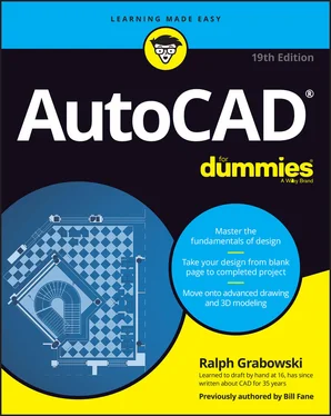
Ralph Grabowski - AutoCAD For Dummies
Здесь есть возможность читать онлайн «Ralph Grabowski - AutoCAD For Dummies» — ознакомительный отрывок электронной книги совершенно бесплатно, а после прочтения отрывка купить полную версию. В некоторых случаях можно слушать аудио, скачать через торрент в формате fb2 и присутствует краткое содержание. Жанр: unrecognised, на английском языке. Описание произведения, (предисловие) а так же отзывы посетителей доступны на портале библиотеки ЛибКат.
- Название:AutoCAD For Dummies
- Автор:
- Жанр:
- Год:неизвестен
- ISBN:нет данных
- Рейтинг книги:5 / 5. Голосов: 1
-
Избранное:Добавить в избранное
- Отзывы:
-
Ваша оценка:
- 100
- 1
- 2
- 3
- 4
- 5
AutoCAD For Dummies: краткое содержание, описание и аннотация
Предлагаем к чтению аннотацию, описание, краткое содержание или предисловие (зависит от того, что написал сам автор книги «AutoCAD For Dummies»). Если вы не нашли необходимую информацию о книге — напишите в комментариях, мы постараемся отыскать её.
AutoCAD For Dummies
AutoCAD For Dummies
AutoCAD For Dummies — читать онлайн ознакомительный отрывок
Ниже представлен текст книги, разбитый по страницам. Система сохранения места последней прочитанной страницы, позволяет с удобством читать онлайн бесплатно книгу «AutoCAD For Dummies», без необходимости каждый раз заново искать на чём Вы остановились. Поставьте закладку, и сможете в любой момент перейти на страницу, на которой закончили чтение.
Интервал:
Закладка:
Understand the difference between command line and Dynamic Input coordinate entry. Second and next points entered at the command line are interpreted differently from those entered at the Dynamic Input tooltip. The second and next points entered at the Dynamic Input tooltip are formatted as polar and are relative to the previously entered coordinate value automatically, unlike at the command line where you must first type @ before the coordinate value for relative coordinates. AutoCAD’s Dynamic Input system displays a lot of the information at the cursor that you used to have to look down to the command line to see. To use Dynamic Input, press F12 to toggle it on and off.
Watch the command line. The command line at times displays additional information about the current command that’s not displayed in the Dynamic Input tooltip. This information might be the current text style or justification, or the active extend mode. I cover using the command line in Chapter 2.
Organize objects on layers. All the objects you draw should be placed on specific layers. For example, annotation objects that communicate design information might be placed on a Notes layer, and the lines that are used to represent a wall might be placed on a Walls layer. I cover layers in Chapter 9.
Introducing the Straight-Line Drawing Commands
As I harp on elsewhere in this book, CAD programs are designed for precision drawing, and you’ll spend a lot of time in AutoCAD drawing objects composed of straight-line segments. The rest of this chapter covers these commands, all of which are found on the Draw panel of the Home tab on the Ribbon. The icons in the left margin match those on the Ribbon:
Line: Draws a series of one or more visually connected straight-line segments; that is, the end of the current segment has the same coordinates as the start of the next segment. Although the lines look like they're physically connected, each segment (piece of a line with endpoints) is in fact a separate object with its own start and endpoints.
PLine: Draws a polyline, which is a series of straight- or curved-line segments (or both) connected as a single object. I’m cheating slightly here because I cover curvy components in Chapter 7, but I don’t want you to have to read about one command in two different places.
RECtang: Provides a convenient way to draw rectangles in a variety of ways as four right-angle polyline segments. AutoCAD has no actual rectangle object.
POLygon: Gives you a convenient way to draw a polyline of many sides in the shape of a regular polygon (a closed shape with all sides and all angles equal).
 The POLygon command may be hidden under the Rectangle button on the Ribbon or vice versa, depending on which button you used last.
The following additional straight-line drawing commands, also available in AutoCAD LT, are found in the drop-down list below the Draw panel:
XLine: Draws a line (known as an ex-line or a construction line) that passes through a point at a specified angle and extends to infinity in both directions.
RAY: Draws a line (known as a ray ) that starts at a point and extends to infinity at a specified angle away from the start point.
 You use the RAY and XLine commands to draw construction lines that guide the construction of other geometry. Using construction lines is less common in AutoCAD than in certain other CAD programs and is far less common than in pencil-and-paper drawings. The many precision techniques in AutoCAD usually provide methods for creating new geometry that are more efficient than adding construction lines to a drawing. In particular, object snap tracking (discussed in Chapter 8) and parametrics (discussed in Chapter 19) usually eliminate the need for construction geometry or even for a mitre line when creating orthographic views.
 Although xlines and rays are infinitely long, they don’t increase the extents of your drawing to infinity. The question of the day is, “Which is longer: an XLine that extends to infinity in both directions or a RAY that extends to infinity in one direction?”
Drawing Lines and Polylines
The Line command works well for many drawing tasks, but the PLine command works better for others. Experience can help you choose which one works best for your design needs. As the PLine command draws polylines, you often hear CAD drafters refer to polylines as a p-lines (rhymes with “bee-lines,” not to be confused with queues in busy restrooms).
Here are the primary differences between the Line and PLine commands:
The Line command draws a series of separate line segments. Even though they appear to be connected onscreen, each one is a separate object. If you move one line segment, none of the other segments you drew at the same time move with it.
The PLine command draws a single, connected, multisegmented object. A polyline is what a line appears to be; each segment is connected with the others to form a single object. If you select any one segment for editing, the change affects the entire polyline, in most cases. Figure 6-1 shows how the same sketch drawn with the Line and the PLine commands responds when you select one of the objects. A polyline is not a pickup line used by parrots in a bar. FIGURE 6-1:Results of drawing with the Line and PLine commands. Use the PLine command rather than the Line command in most cases where you need to draw a series of connected line segments. If you’re drawing a series of end-to-end segments, those segments may well be logically connected. For example, they might represent the outline of a single object or a continuous pathway. If the segments are connected logically, it makes sense to keep them connected in AutoCAD. The most obvious practical benefit of grouping segments into a polyline is that many editing operations are more efficient when you use polylines. When you select any segment in a polyline for editing, the entire polyline is selected. As covered in Chapter 19, using parametrics on line segments can often produce the same results as using the PLine command.
The PLine command can draw curved segments as well as straight ones. If you want a combination of separate linear and curved segments, you must switch between the Line and Arc commands. (I cover arcs in Chapter 7.) Using the PLine command, though, you can switch between linear or circular-curve segments in a single polyline.
A polyline can have width. Polyline segment width is visually similar to the lineweight object property in AutoCAD (which I discuss in Chapter 9) except that polyline width can vary from segment to segment, and individual segments can be tapered. Polylines are often used for the copper conductors on electronic printed circuit boards.
Polylines can be smooth curves. After drawing a polyline, you can use the PEdit command to automatically reshape the polyline into a smooth, flowing curve based on the vertex points you selected. I touch on this topic in Chapter 11.
The following sections show you how to create a line and a polyline.
Toeing the line
Unlike many AutoCAD drawing commands, Line offers limited options. It has a Close option only to create one more segment back to the first point you picked in the current run of the command, and it has an Undo option to remove the most recently drawn segment. You can repeat the Undo option back to the start of the current run of the command.
Читать дальшеИнтервал:
Закладка:
Похожие книги на «AutoCAD For Dummies»
Представляем Вашему вниманию похожие книги на «AutoCAD For Dummies» списком для выбора. Мы отобрали схожую по названию и смыслу литературу в надежде предоставить читателям больше вариантов отыскать новые, интересные, ещё непрочитанные произведения.
Обсуждение, отзывы о книге «AutoCAD For Dummies» и просто собственные мнения читателей. Оставьте ваши комментарии, напишите, что Вы думаете о произведении, его смысле или главных героях. Укажите что конкретно понравилось, а что нет, и почему Вы так считаете.


