Stephen Rolt - Optical Engineering Science
Здесь есть возможность читать онлайн «Stephen Rolt - Optical Engineering Science» — ознакомительный отрывок электронной книги совершенно бесплатно, а после прочтения отрывка купить полную версию. В некоторых случаях можно слушать аудио, скачать через торрент в формате fb2 и присутствует краткое содержание. Жанр: unrecognised, на английском языке. Описание произведения, (предисловие) а так же отзывы посетителей доступны на портале библиотеки ЛибКат.
- Название:Optical Engineering Science
- Автор:
- Жанр:
- Год:неизвестен
- ISBN:нет данных
- Рейтинг книги:3 / 5. Голосов: 1
-
Избранное:Добавить в избранное
- Отзывы:
-
Ваша оценка:
Optical Engineering Science: краткое содержание, описание и аннотация
Предлагаем к чтению аннотацию, описание, краткое содержание или предисловие (зависит от того, что написал сам автор книги «Optical Engineering Science»). Если вы не нашли необходимую информацию о книге — напишите в комментариях, мы постараемся отыскать её.
Offers a comprehensive review of the topic of optical engineering Covers topics such as optical fibers, waveguides, aspheric surfaces, Zernike polynomials, polarisation, birefringence and more Targets engineering professionals and students Filled with illustrative examples and mathematical equations Written for professional practitioners, optical engineers, optical designers, optical systems engineers and students,
offers an authoritative guide that covers the broad range of optical design and optical metrology topics and their applications.
Optical Engineering Science — читать онлайн ознакомительный отрывок
Ниже представлен текст книги, разбитый по страницам. Система сохранения места последней прочитанной страницы, позволяет с удобством читать онлайн бесплатно книгу «Optical Engineering Science», без необходимости каждый раз заново искать на чём Вы остановились. Поставьте закладку, и сможете в любой момент перейти на страницу, на которой закончили чтение.
Интервал:
Закладка:

Having established an additional way of describing aberrations in terms of the violation of Fermat's principle, the question is what is the particular significance and utility of this approach? The answer is that, when expressed in terms of the OPD, aberrations are additive through a system. As a consequence of this, this treatment provides an extremely powerful general description of aberrations and, in particular, third order aberrations. Broadly, aberrations can be computed for individual system elements, such as surfaces, mirrors, or lenses and applied additively to the system as a whole. This generality and flexibility is not provided by a consideration of transverse aberrations.
There is a correspondence between transverse aberration and OPD. This is illustrated in Figure 3.6. At this point, we introduce a concept that is related to that of OPD, namely wavefront error ( WFE ). We must remember that, according to the wave description, the rays we trace through the system represent normals to the relevant wavefront. The wavefront itself originates from a single object point and represents a surface of equal phase. As such, the wavefront represents a surface of equal optical path length. For an aberrated optical system, the surface normals (rays) do not converge on a single point. In Figure 3.6, this surface is shown as a solid line. A hypothetical spherical surface, shown as a dashed line, is now added to represent rays converging on the paraxial focus. This surface intersects the real surface at the chief ray position. The distance between these two surfaces is the WFE.
In terms of the sign convention, the wavefront error, WFE, is given by:

The sign convention is important, as it now concurs with the definition of OPD. As the wavefronts form surfaces of constant optical path length, there is a direct correspondence between OPD and WFE. A positive OPD indicates the optical path of the ray at the reference sphere is lessthan that of the chief ray. Therefore, this ray has to travel a small positive distance to ‘catch up’ with the chief ray to maintain phase equality. Hence, the WFE is also positive.
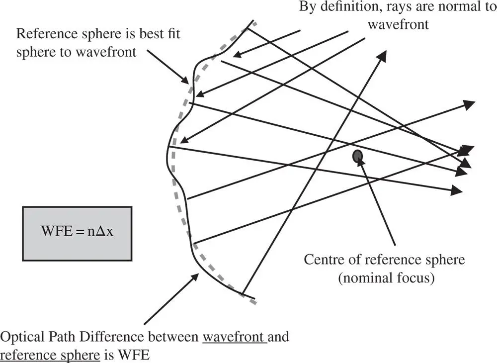
Figure 3.6 Wavefront representation of aberration.
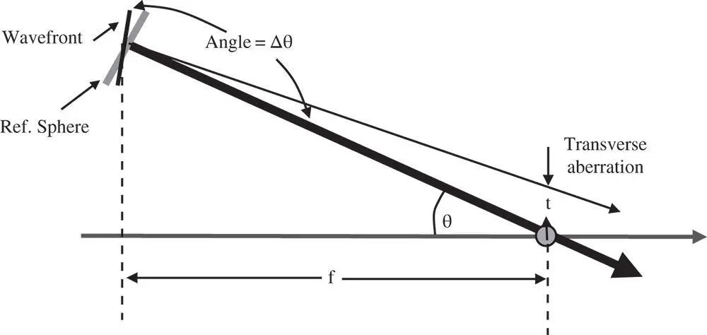
Figure 3.7 Simplified wavefront and ray geometry.
Both OPD and WFE quantify the violation of Fermat's principle in the same way. OPD is generally used to describe the path length difference of a specific ray. WFE tends to be used when describing OPD variation across an assembly of rays, specifically across a pupil. The concept of WFE enables us to establish the relationship between OPD and transverse aberration in that it helps define the link between wave (phase and path length) geometry and ray geometry. This is shown in Figure 3.7. It is clear that the transverse aberration is related to the angular difference between the wavefront and reference sphere surfaces.
We now describe the WFE, Φ, as a function of the reference sphere (paraxial ray) angle, θ. The radius of the reference sphere (distance to the paraxial focus) is denoted by f . This allows us to calculate the difference in angle, Δθ, between the real and paraxial rays. This is simply equal to the difference in local slope between the two surfaces.
(3.9) 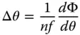
n is the medium refractive index .
In this analysis, the WFE represents the difference between the real and reference surfaces with the positive axial direction represented by the propagation direction (from object to image). In this convention, the WFE has the opposite sign to the OPD. The transverse aberration, t, can be derived from simple trigonometry.
(3.10) 
If θ describes the angle the ray makes to the chief ray, then Eq. (3.10)may be reformed in terms of the numerical aperture, NA. The numerical aperture is equal to nsinθ, and Eq. (3.11)may be recast as:
(3.11) 
So, the transverse aberration may be represented by the first differential of the WFE with respect to the numerical aperture. In terms of third order aberration theory, the numerical aperture of an individual ray is directly proportional to the normalised pupil function, p . If the overall system, or marginal ray, numerical aperture is NA 0, then the individual ray numerical aperture is simply NA 0 p . The transverse aberration is then given by:
(3.12) 
Equation (3.12)provides a simple direct relationship between OPD and transverse aberration. Of course, we know that, for third order aberration, the transverse aberration is proportional to the third power of the pupil function, p. If this is the case, then it is apparent, from Eq. (3.12), that the OPD is proportional to the fourth power of the pupil function. So, for third order aberration, the transverse aberration shows a third power dependence upon the pupil function whereas the OPD shows a fourth power dependence.
Applying these arguments to the analysis of the simple on-axis example illustrated earlier, with the object placed at the infinite conjugate, then the WFE can be represented by the following equation:
(3.13) 
p is the normalised pupil function .
Figure 3.8shows a plot of the OPD against the normalised pupil function; such a plot is referred to as an OPD fan.
Despite the fact that this simple aberration has a quartic dependence on the pupil function, it is still referred to as third order aberration after the transverse aberration dependence. As with the optimisation of transverse aberration, the OPD can be balanced by applying defocus to offset the aberration. We saw earlier that a simple defocus produces a linear term in the transverse aberration. Referring to Eq. (3.12), it is clear that defocus may be represented by a quadratic term. Equation (3.14)describes the OPD when some defocus has been added to the initial aberration.
(3.14) 
An OPD fan with aberration plus balancing defocus is shown in Figure 3.9.
Читать дальшеИнтервал:
Закладка:
Похожие книги на «Optical Engineering Science»
Представляем Вашему вниманию похожие книги на «Optical Engineering Science» списком для выбора. Мы отобрали схожую по названию и смыслу литературу в надежде предоставить читателям больше вариантов отыскать новые, интересные, ещё непрочитанные произведения.


Обсуждение, отзывы о книге «Optical Engineering Science» и просто собственные мнения читателей. Оставьте ваши комментарии, напишите, что Вы думаете о произведении, его смысле или главных героях. Укажите что конкретно понравилось, а что нет, и почему Вы так считаете.