Jason Gumster - Blender For Dummies
Здесь есть возможность читать онлайн «Jason Gumster - Blender For Dummies» — ознакомительный отрывок электронной книги совершенно бесплатно, а после прочтения отрывка купить полную версию. В некоторых случаях можно слушать аудио, скачать через торрент в формате fb2 и присутствует краткое содержание. Жанр: unrecognised, на английском языке. Описание произведения, (предисловие) а так же отзывы посетителей доступны на портале библиотеки ЛибКат.
- Название:Blender For Dummies
- Автор:
- Жанр:
- Год:неизвестен
- ISBN:нет данных
- Рейтинг книги:5 / 5. Голосов: 1
-
Избранное:Добавить в избранное
- Отзывы:
-
Ваша оценка:
Blender For Dummies: краткое содержание, описание и аннотация
Предлагаем к чтению аннотацию, описание, краткое содержание или предисловие (зависит от того, что написал сам автор книги «Blender For Dummies»). Если вы не нашли необходимую информацию о книге — напишите в комментариях, мы постараемся отыскать её.
Author Jason van Gumster shares his insight as an independent animator and digital artist to help Blender newcomers turn their ideas into three-dimensional drawings. From exporting and sharing scenes to becoming a part of the Blender community, this accessible book covers it all!
Create 3D characters—no experience required Build scenes with texture and real lighting features Animate your creations and share them with the world Avoid common rookie mistakes This book is the ideal starting place for newcomers to the world of 3D modeling and animation.
Blender For Dummies — читать онлайн ознакомительный отрывок
Ниже представлен текст книги, разбитый по страницам. Система сохранения места последней прочитанной страницы, позволяет с удобством читать онлайн бесплатно книгу «Blender For Dummies», без необходимости каждый раз заново искать на чём Вы остановились. Поставьте закладку, и сможете в любой момент перейти на страницу, на которой закончили чтение.
Интервал:
Закладка:
Selecting vertices, edges, and faces
Regardless of how you get into Edit mode, once you’re there the cube changes color and dots form at each of the cube’s corners. Each dot is a vertex . The line that forms between two vertices is an edge . A face in Blender is a polygon that has been formed by three or more connecting edges.
 In the past, faces in Blender and other applications were limited to only three-sided and four-sided polygons, often referred to as tris (pronounced like tries ) and quads . Since that time, Blender — like many other programs — gained support for something called an ngon that can have a virtually limitless number of sides. But don’t let Blender’s ngon functionality go to your head. There still are some limitations and caveats, as covered in the “A word on ngons” sidebar later in this chapter. Generally, you should think of ngons as a “process” tool. With some exceptions, like architectural models, a finished model should only consist of just three- and four-sided faces. In fact, most detailed character models are made almost completely with quads and an occasional triangle, and all 3D geometry is reduced to triangles when it gets to your computer hardware.
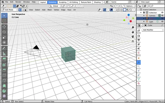
FIGURE 4-2:The Modeling workspace gives you quick access to Edit mode and a screen layout that’s more specifically geared for modeling.


 For polygon editing, you can use three different types of Edit modes, sometimes called selection modes: Vertex Select, Edge Select, and Face Select. By default, the first time you tab into Edit mode, you’re in Vertex Select mode.
Two visual cues in the Blender interface clue you in to what selection mode you’re using. First, for Vertex Select mode, you can see the individual vertices in the mesh. Second, as Figure 4-3 shows, three new buttons appear in the 3D Viewport’s header when you’re in Edit mode. The button on the left (it has an icon of a cube with a dot over one corner) is enabled, indicating that you’re in Vertex Select mode.

FIGURE 4-3:The Edit mode Select buttons.
To the right of the Vertex Select button is a button displaying an icon of a cube with a highlighted edge. Click this button to activate Edge Select mode. When you do, the vertices are no longer visible on your mesh. Clicking the last button in this block, which has an icon of a cube with one side marked in solid, activates Face Select mode. When Face Select mode is active, vertices aren’t visible, and each polygon in your mesh can be selected as a single unit.
Now, you may notice that the selection mode buttons are blocked together, kind of like they can be used together. That’s because they can! In any given Edit mode session you can have multiple selection modes active at the same time. Simply Shift+left-click the selection mode buttons to get this functionality. Some Blender modelers like to have Vertex Select and Edge Select modes active at the same time to speed up their workflow. This combined selection mode gives them immediate control at the vertex and edge level, and you can easily select the faces by Box-selecting across two edges.
Blender also has some handy hotkeys for quickly switching between vertex, edge, and face selection. They’re the numbers 1, 2, and 3 across the top of your keyboard ( not the Numpad!). A handy mnemonic to help you remember which key belongs to which selection mode is to remember how many vertices make up each one. A vertex is a single unit, so the hotkey for Vertex Select is 1. It takes two vertices to make an edge, so the hotkey for Edge Select is 2. And a face consists of three or more vertices, so the hotkey for Face Select is 3. You can activate Combo Select by holding Shift while pressing any of these hotkeys (for example, if you’re in Vertex Select and you also want to be in Edge Select, press Shift+2). Figure 4-4 shows the default cube in each of the select modes, as well as a Combo Select mode.
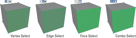
FIGURE 4-4:Vertex Select, Edge Select, Face Select, and Combo Select modes.

 As Figure 4-4 shows, it can be a little bit tricky to tell whether you’re in Edge Select or Face Select at a glance. To make things a little more clear, I recommend that you enable face centers (sometimes called face dots ) in the Viewport Overlays roll-out menu in the header of the 3D Viewport. Expand the menu by clicking the down arrow that’s to the right of the Viewport Overlays icon and you should see a menu like the one in Figure 4-5.
This menu is large, but about halfway down, under the label of Mesh Edit Mode, there are a series of check boxes. One of which is a check box somewhat vaguely labeled Center. Enable that check box and you should see a small dot appear at the center of your faces while you’re in Face Select mode. That should give you a little bit more of a visual cue to indicate which mode you’re in.
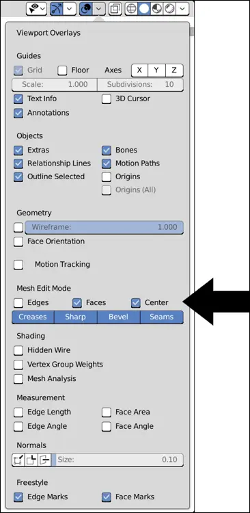
FIGURE 4-5:Use the Viewport Overlays roll-out menu to enable face centers so it’s easier to tell what selection mode you’re using.
By default, the first time you tab into Edit mode on a newly added object, all vertices/edges/faces (sometimes called components ) are selected. Selecting things in Edit mode works just like selecting anywhere else:
Left-click any component to select it.
Select and deselect multiple components by Shift+left-clicking them.
Select all components by pressing A.
Deselect all components by pressing Alt+A or clicking in an empty space in the 3D Viewport.
Use one of the select tools from the Toolbar (left-click and hold on the Select tool icon in the Toolbar to see all available select tools): Select: This tool only allows selecting by clicking and Shift+left-clicking on individual components. Box Select: Left-click and drag to draw a box around the components you want to select. Shift+left-click and drag to add to your select. Ctrl+left-click and drag to remove from your selection set. Circle Select: This tool is sometimes called brush select because selection is a lot like painting. Any vertices that you run your mouse cursor over while holding down the left mouse button are selected. Shift+left-click and Ctrl+left-click work like they do with the Box Select tool. You can change the size of your Circle Select’s “brush” by adjusting the Radius value in the Active Tool tab of the Properties editor. Lasso Select: The Lasso Select tool allows you to draw an arbitrary shape in the 3D Viewport using left-click and drag. Any component within the shape you draw is selected. Shift+left-click and Ctrl+left-click work like they do with the preceding two selection tools.
Читать дальшеИнтервал:
Закладка:
Похожие книги на «Blender For Dummies»
Представляем Вашему вниманию похожие книги на «Blender For Dummies» списком для выбора. Мы отобрали схожую по названию и смыслу литературу в надежде предоставить читателям больше вариантов отыскать новые, интересные, ещё непрочитанные произведения.


Обсуждение, отзывы о книге «Blender For Dummies» и просто собственные мнения читателей. Оставьте ваши комментарии, напишите, что Вы думаете о произведении, его смысле или главных героях. Укажите что конкретно понравилось, а что нет, и почему Вы так считаете.