Mark W. Spong - Robot Modeling and Control
Здесь есть возможность читать онлайн «Mark W. Spong - Robot Modeling and Control» — ознакомительный отрывок электронной книги совершенно бесплатно, а после прочтения отрывка купить полную версию. В некоторых случаях можно слушать аудио, скачать через торрент в формате fb2 и присутствует краткое содержание. Жанр: unrecognised, на английском языке. Описание произведения, (предисловие) а так же отзывы посетителей доступны на портале библиотеки ЛибКат.
- Название:Robot Modeling and Control
- Автор:
- Жанр:
- Год:неизвестен
- ISBN:нет данных
- Рейтинг книги:4 / 5. Голосов: 2
-
Избранное:Добавить в избранное
- Отзывы:
-
Ваша оценка:
Robot Modeling and Control: краткое содержание, описание и аннотация
Предлагаем к чтению аннотацию, описание, краткое содержание или предисловие (зависит от того, что написал сам автор книги «Robot Modeling and Control»). Если вы не нашли необходимую информацию о книге — напишите в комментариях, мы постараемся отыскать её.
, students will cover the theoretical fundamentals and the latest technological advances in robot kinematics. With so much advancement in technology, from robotics to motion planning, society can implement more powerful and dynamic algorithms than ever before. This in-depth reference guide educates readers in four distinct parts; the first two serve as a guide to the fundamentals of robotics and motion control, while the last two dive more in-depth into control theory and nonlinear system analysis.
With the new edition, readers gain access to new case studies and thoroughly researched information covering topics such as:
● Motion-planning, collision avoidance, trajectory optimization, and control of robots
● Popular topics within the robotics industry and how they apply to various technologies
● An expanded set of examples, simulations, problems, and case studies
● Open-ended suggestions for students to apply the knowledge to real-life situations
A four-part reference essential for both undergraduate and graduate students,
serves as a foundation for a solid education in robotics and motion planning.
Robot Modeling and Control — читать онлайн ознакомительный отрывок
Ниже представлен текст книги, разбитый по страницам. Система сохранения места последней прочитанной страницы, позволяет с удобством читать онлайн бесплатно книгу «Robot Modeling and Control», без необходимости каждый раз заново искать на чём Вы остановились. Поставьте закладку, и сможете в любой момент перейти на страницу, на которой закончили чтение.
Интервал:
Закладка:
Since the origin of a coordinate frame is also a point in space, we can assign coordinates that represent the position of the origin of one coordinate frame with respect to another. In Figure 2.1, for example, we may have
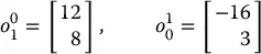
Thus, o 0 1specifies the coordinates of the point o 1relative to frame 0 and o 1 0specifies the coordinates of the point 0 0relative to frame 1. In cases where there is only a single coordinate frame, or in which the reference frame is obvious, we will often omit the superscript. This is a slight abuse of notation, and the reader is advised to bear in mind the difference between the geometric entity called p and any particular coordinate vector that is assigned to represent p . The former is independent of the choice of coordinate frames, while the latter obviously depends on the choice of coordinate frames.
While a point corresponds to a specific location in space, a vectorspecifies a direction and a magnitude. Vectors can be used, for example, to represent displacements or forces. Therefore, while the point p is not equivalent to the vector v 1, the displacement from the origin o 0to the point p is given by the vector v 1. In this text, we will use the term vectorto refer to what are sometimes called free vectors, that is, vectors that are not constrained to be located at a particular point in space. Under this convention, it is clear that points and vectors are not equivalent, since points refer to specific locations in space, but a free vector can be moved to any location in space. Thus, two vectors are equal if they have the same direction and the same magnitude.
When assigning coordinates to vectors, we use the same notational convention that we used when assigning coordinates to points. Thus, v 1and v 2are geometric entities that are invariant with respect to the choice of coordinate frames, but the representation by coordinates of these vectors depends directly on the choice of reference coordinate frame. In the example of Figure 2.1, we would obtain
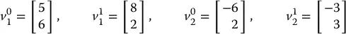
In order to perform algebraic manipulations using coordinates, it is essential that all coordinate vectors be defined with respect to the same coordinate frame. In the case of free vectors, it is enough that they be defined with respect to “parallel” coordinate frames, that is, frames whose respective coordinate axes are parallel, since only their magnitude and direction are specified and not their absolute locations in space.
Using this convention, an expression of the form  , where
  and
and  are as in Figure 2.1, is not defined since the frames o 0 x 0 y 0and o 1 x 1 y 1are not parallel. Thus, we see a clear need not only for a representation system that allows points to be expressed with respect to various coordinate frames, but also for a mechanism that allows us to transform the coordinates of points from one coordinate frame to another. Such coordinate transformations are the topic for much of the remainder of this chapter.
2.2 Representing Rotations
In order to represent the relative position and orientation of one rigid body with respect to another, we attach coordinate frames to each body, and then specify the geometric relationship between these coordinate frames. In Section 2.1 we saw how one can represent the position of the origin of one frame with respect to another frame. In this section, we address the problem of describing the orientation of one coordinate frame relative to another frame. We begin with the case of rotations in the plane, and then generalize our results to the case of rotations in a three-dimensional space.
2.2.1 Rotation in the Plane
Figure 2.2shows two coordinate frames, with frame o 1 x 1 y 1obtained by rotating frame o 0 x 0 y 0by an angle θ . Perhaps the most obvious way to represent the relative orientation of these two frames is merely to specify the angle of rotation θ . There are two immediate disadvantages to such a representation. First, there is a discontinuity in the mapping from relative orientation to the value of θ in a neighborhood of θ = 0. In particular, for θ = 2 π − ε , small changes in orientation can produce large changes in the value of θ , for example, a rotation by ε causes θ to “wrap around” to zero. Second, this choice of representation does not scale well to the three-dimensional case.
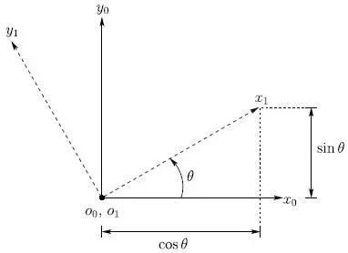
Figure 2.2 Coordinate frame o 1 x 1 y 1is oriented at an angle θ with respect to o 0 x 0 y 0.
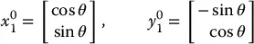
A slightly less obvious way to specify the orientation is to specify the coordinate vectors for the axes of frame o 1 x 1 y 1with respect to coordinate frame o 0 x 0 y 0:
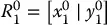
in which  and
and  are the coordinates in frame o 0 x 0 y 0of unit vectors x 1and y 1, respectively. 1A matrix in this form is called a rotation matrix. Rotation matrices have a number of special properties that we will discuss below.
In the two-dimensional case, it is straightforward to compute the entries of this matrix. As illustrated in Figure 2.2,
which gives
(2.1) 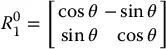
Note that we have continued to use the notational convention of allowing the superscript to denote the reference frame. Thus,  is a matrix whose column vectors are the coordinates of the unit vectors along the axes of frame o 1 x 1 y 1expressed relative to frame o 0 x 0 y 0.
Although we have derived the entries for  in terms of the angle θ , it is not necessary that we do so. An alternative approach, and one that scales nicely to the three-dimensional case, is to build the rotation matrix by projecting the axes of frame o 1 x 1 y 1onto the coordinate axes of frame o 0 x 0 y 0. Recalling that the dot product of two unit vectors gives the projection of one onto the other, we obtain
Интервал:
Закладка:
Похожие книги на «Robot Modeling and Control»
Представляем Вашему вниманию похожие книги на «Robot Modeling and Control» списком для выбора. Мы отобрали схожую по названию и смыслу литературу в надежде предоставить читателям больше вариантов отыскать новые, интересные, ещё непрочитанные произведения.


Обсуждение, отзывы о книге «Robot Modeling and Control» и просто собственные мнения читателей. Оставьте ваши комментарии, напишите, что Вы думаете о произведении, его смысле или главных героях. Укажите что конкретно понравилось, а что нет, и почему Вы так считаете.