Joel P. Dunsmore - Handbook of Microwave Component Measurements
Здесь есть возможность читать онлайн «Joel P. Dunsmore - Handbook of Microwave Component Measurements» — ознакомительный отрывок электронной книги совершенно бесплатно, а после прочтения отрывка купить полную версию. В некоторых случаях можно слушать аудио, скачать через торрент в формате fb2 и присутствует краткое содержание. Жанр: unrecognised, на английском языке. Описание произведения, (предисловие) а так же отзывы посетителей доступны на портале библиотеки ЛибКат.

- Название:Handbook of Microwave Component Measurements
- Автор:
- Жанр:
- Год:неизвестен
- ISBN:нет данных
- Рейтинг книги:5 / 5. Голосов: 1
-
Избранное:Добавить в избранное
- Отзывы:
-
Ваша оценка:
Handbook of Microwave Component Measurements: краткое содержание, описание и аннотация
Предлагаем к чтению аннотацию, описание, краткое содержание или предисловие (зависит от того, что написал сам автор книги «Handbook of Microwave Component Measurements»). Если вы не нашли необходимую информацию о книге — напишите в комментариях, мы постараемся отыскать её.
Handbook of Microwave Component Measurements — читать онлайн ознакомительный отрывок
Ниже представлен текст книги, разбитый по страницам. Система сохранения места последней прочитанной страницы, позволяет с удобством читать онлайн бесплатно книгу «Handbook of Microwave Component Measurements», без необходимости каждый раз заново искать на чём Вы остановились. Поставьте закладку, и сможете в любой момент перейти на страницу, на которой закончили чтение.
Интервал:
Закладка:
(2.28) 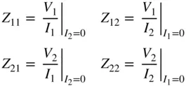
But, the conditions for measurement of these parameters directly cannot be realized in RF and microwave systems for several key reasons, listed here:
1 When the ports of an RF circuit are left open, fringing capacitance from the center pin of the RF terminal to ground reduces the impedance at high frequency, and phase shift from the DUT reference plane makes the practical value of an open circuit deviate from the ideal.
2 The measuring equipment to sense V1, I1, V2, and I2 has a parasitic impedance to ground, which also shunts some of the terminal current. At the driving port, this means that the measured current does not match the actual current into the DUT, and at the open port it means that while being measured, the output impedance does not match that of an open circuit
3 For many active devices, the DUT is only conditionally stable and may oscillate if larger reflections are presented at the ports. Phase shift of the open circuit from the terminal port to the DUT active device can cause the reflection to take on almost any phase, and it ensures that at some frequency the reflection at the port will be such that the device will oscillate. This is perhaps the primary reason for S‐parameters being used on active devices; they provide a consistent low‐reflection load, which in general prevents oscillations of the DUT.
Of course, Z‐parameters are not restricted to just two ports, and the Z‐parameters can be put in a matrix form of
(2.29) 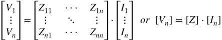
where [ Z ] is called the Z‐matrix.
The Z‐matrix and S‐matrix can be computed from each other, given the reference impedance is known for the S‐parameters, and the same on each port; then
(2.30) 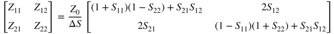
where Δ S = (1 − S 11)(1 − S 22) − S 21 S 12
(2.31) 
where Δ Z = ( Z 11+ Z 0)( Z 22+ Z 0) − Z 21 Z 12
An attribute of the Z‐matrix is that if a DUT is lossless, the Z‐matrix will contain only pure imaginary numbers; this is commonly found in filter design applications. If Z 21= Z 12 ,then the DUT is reciprocal, and if also Z 11= Z 22, the network is symmetrical. Note that in general Z In≠ Z 11except for a 1‐port network. Z Inrepresents the ratio of V 1and I 1for the DUT as it is terminated, normally in the system reference impedance Z 0, where Z 11is the ratio of V 1and I 1when all the other ports are open circuited, a not very useful case in practice. Another important attribute of the Z‐matrix is that its values do not depend upon the measurement system, unlike S‐parameters whose values depend upon the reference impedance for each port and whose values can change for the same network, if these reference impedances change. Put another way, the S11 of a 50 Ω load will be quite different when measured in a 75 Ω reference impedance, but the Z‐parameters will not change.
2.6.2 Y‐Parameters, or Short‐Circuit Admittance Parameters
Y‐parameters are essentially an inverse, of Z‐parameters, and in fact the Y‐matrix is the inverse of the Z‐matrix. The definition of Y‐parameters is derived from
(2.32) 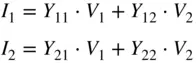
From this, the common description of Y‐parameters are
(2.33) 
The Y‐parameters can also be defined for more than 2‐port devices, and the matrix form is
(2.34) 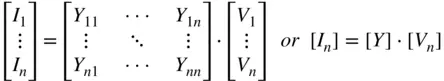
where the Y‐matrix refers to [ Y ]. The Y‐matrix is related to the Z‐matrix through its inverse, as
(2.35) 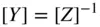
The conversions between the S‐matrix and the Y‐matrix are
(2.36) 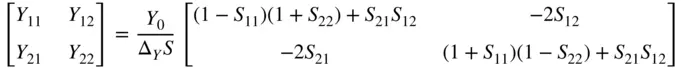
where Δ Y S = (1 + S 11)(1 + S 22) − S 21 S 12
(2.37) 
where Δ Y = ( Y 0+ Y 11)( Y 0+ Y 22) − Y 21 Y 12
2.6.3 ABCD Parameters
Just as the T‐parameters provide for easy concatenation of devices using a and b waves, a similar matrix representation can be used when the terminal characteristics are defined in terms of voltage and current. These are sometimes called transfer parameters (reminiscent of the T‐parameters) or chain parameters as networks can be chained together in a matrix multiplication manner.
The functional definition of ABCD parameters is found in at least two different forms, one of which is
(2.38) 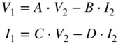
The second form replaces the minus sign with a plus sign with resulting changes in the derived values.
From Eq. 2.38the values for ABCD parameters can be defined as
(2.39) 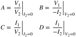
The transformations between the ABCD‐matrix and the S‐matrix are
(2.40) 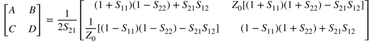
(2.41) 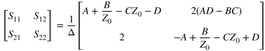
where 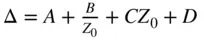
2.6.4 H‐Parameters or Hybrid Parameters
Because of its intrinsic transfer function, as a voltage‐controlled current source, transistor performance has often been described using hybrid parameters. Their functional definition is
Читать дальшеИнтервал:
Закладка:
Похожие книги на «Handbook of Microwave Component Measurements»
Представляем Вашему вниманию похожие книги на «Handbook of Microwave Component Measurements» списком для выбора. Мы отобрали схожую по названию и смыслу литературу в надежде предоставить читателям больше вариантов отыскать новые, интересные, ещё непрочитанные произведения.


Обсуждение, отзывы о книге «Handbook of Microwave Component Measurements» и просто собственные мнения читателей. Оставьте ваши комментарии, напишите, что Вы думаете о произведении, его смысле или главных героях. Укажите что конкретно понравилось, а что нет, и почему Вы так считаете.