Joel P. Dunsmore - Handbook of Microwave Component Measurements
Здесь есть возможность читать онлайн «Joel P. Dunsmore - Handbook of Microwave Component Measurements» — ознакомительный отрывок электронной книги совершенно бесплатно, а после прочтения отрывка купить полную версию. В некоторых случаях можно слушать аудио, скачать через торрент в формате fb2 и присутствует краткое содержание. Жанр: unrecognised, на английском языке. Описание произведения, (предисловие) а так же отзывы посетителей доступны на портале библиотеки ЛибКат.

- Название:Handbook of Microwave Component Measurements
- Автор:
- Жанр:
- Год:неизвестен
- ISBN:нет данных
- Рейтинг книги:5 / 5. Голосов: 1
-
Избранное:Добавить в избранное
- Отзывы:
-
Ваша оценка:
Handbook of Microwave Component Measurements: краткое содержание, описание и аннотация
Предлагаем к чтению аннотацию, описание, краткое содержание или предисловие (зависит от того, что написал сам автор книги «Handbook of Microwave Component Measurements»). Если вы не нашли необходимую информацию о книге — напишите в комментариях, мы постараемся отыскать её.
Handbook of Microwave Component Measurements — читать онлайн ознакомительный отрывок
Ниже представлен текст книги, разбитый по страницам. Система сохранения места последней прочитанной страницы, позволяет с удобством читать онлайн бесплатно книгу «Handbook of Microwave Component Measurements», без необходимости каждый раз заново искать на чём Вы остановились. Поставьте закладку, и сможете в любой момент перейти на страницу, на которой закончили чтение.
Интервал:
Закладка:
2.4.1.2 Impedance Transformation
One aspect of rotation on the Smith chart that is often misunderstood is that the rotation around the center of the chart for a transmission line delay occurs only if the transmission line impedance matches the reference impedance of the Smith chart. Consider a case of a termination consisting of a 25 Ω resistor to ground, shunted by a 3 pF capacitor, and evaluated from DC to 10 GHz. The impedance trajectory is shown in the light trace in Figure 2.37, which shows a small deviation from 25 Ω due to the shunt capacitance. The darker trace shows the same impedance, but at the end of a transmission line that has 180° of phase shift at 10 GHz. The value of the impedance trajectory centers on 50 Ω, and the value of the trace at 180° phase shift matches that exactly of zero phase shift. At the frequency where the phase shifts 90° due to the transmission line (5.4 GHz) plus the slight phase shift of the DUT, the impedance is nearly 100 Ω. This is a well‐known aspect of ¼ wave (or 90°, or λ /4) transmission line transformers. If impedance of the line is Z 0, then the impedance at the end of a ¼ wave section is
(2.16) 
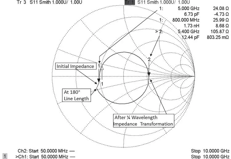
Figure 2.37 An impedance value rotated by 180° 50 Ω line.
One consequence of this is that the maximum deviation of impedance due to a transmission line depends completely on the impedance of the transmission line. Figure 2.38shows the Smith chart trajectories for the same termination, but this time with a 12.5 Ω line, a 25 Ω line, and a 100 Ω line before the termination. Of course, at 180°, no transformation of impedance takes place, and the impedance value at the end of the line is identical to that at the 0° phase shift. It is interesting to note that the smallest deviation of impedance is for the case where the line matches the impedance of the termination, rather than matching the system impedance, as in Figure 2.37.
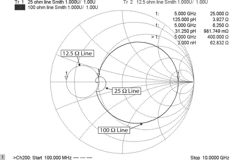
Figure 2.38 25 Ω termination proceeded by half‐wavelength segments of 12.5, 25, and 100 Ω lines.
The other important aspect to note is that when the transmission line is of greater impedance than Z L, the resulting impedance will transform to a higher value, while when the transmission line is of lower impedance, the resulting impedance will be lower than Z L.
2.4.2 Transforming S‐Parameters to Other Impedances
While it is most common to define S‐parameters in a 50 Ω impedance, or 75 Ω for cable‐television applications, situations arise where it is necessary to define an S‐parameter matrix in other than 50 Ω, or to have it defined with 50 Ω on one port and with a different impedance on another port. This requirement occurs for matching circuits, or impedance transformers, as well as the use of waveguide adapters where it is common practice to define the terminal impedance as 1 Ω. Unfortunately, while S‐parameter definitions don't prohibit different impedances on different ports, the most common data files for S‐parameters, the so‐called Touchstone™ or S2P files, provide for only a single impedance in their definition. (Recently a second revision of the S2P file format has been defined that allows different impedances on different ports, but it has not yet been widely implemented.) Thus, it is often necessary to transform S‐parameters from one reference impedance to another. If the complete S‐parameter matrix is available, then a matrix transformation (Tippet and Speciale 1982) can be used to convert the impedance of by applying
(2.17) 
where 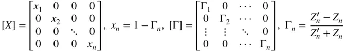
This is a generalized formula so that an impedance, [ Z n], may be defined for any port of the original [ S ] matrix and any other impedance  may defined for any other port for the new [ S ′] matrix. However, the two most common cases are where the transformation occurs for all impedances at the ports being equal, so that each element in the X matrix and Γ matrix are identical, and where in the 2‐port case only one impedance is transformed, as when the S‐parameters of a network are defined in two different impedances.
If the measurement system impedance is pure‐real, an alternative method for obtaining S‐parameters at a different real impedance than the measurement system is to de‐embed an ideal transformer at each port, with the turns ratio set to the square root of the impedance change. De‐embedding methods are discussed in Chapter 9.
2.4.3 Concatenating Circuits and T‐Parameters
In many instances, it is convenient to concatenate devices, and signal‐flow charts provide a useful tool for understanding the interactions and determining the resulting S‐parameter matrix. With appropriate transformations, the concatenation of S‐parameter devices can be greatly simplified. One such transformation is from S‐parameters to T‐parameters, which also depend upon the wave functions but in a different relationship.
Figure 2.39shows a concatenation of two devices, with a and b waves for each independently identified. Using normal signal‐flow properties, the combined S‐parameters of two devices is
(2.18) 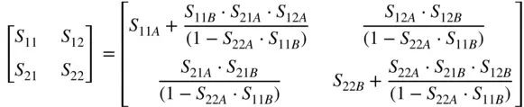
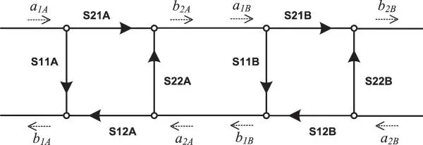
Figure 2.39 Concatenation of two devices.
However, signal‐flow‐graph techniques get tedious for concatenating a long series of devices, and other transformations make this work easier and more programmatic.
The T‐parameters (Keysight Application Note 154 n.d.-b) create a new functional relationship between input and output waves, with the independent variables being waves on the right and the dependent variables being waves on the left.
(2.19) 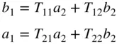
Or in the matrix form
(2.20) 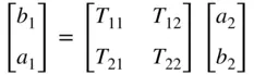
From this, the T‐matrix describing the first and second devices are
(2.21) 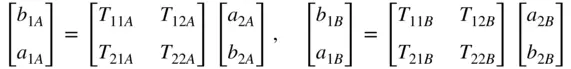
Интервал:
Закладка:
Похожие книги на «Handbook of Microwave Component Measurements»
Представляем Вашему вниманию похожие книги на «Handbook of Microwave Component Measurements» списком для выбора. Мы отобрали схожую по названию и смыслу литературу в надежде предоставить читателям больше вариантов отыскать новые, интересные, ещё непрочитанные произведения.


Обсуждение, отзывы о книге «Handbook of Microwave Component Measurements» и просто собственные мнения читателей. Оставьте ваши комментарии, напишите, что Вы думаете о произведении, его смысле или главных героях. Укажите что конкретно понравилось, а что нет, и почему Вы так считаете.