Jing-Feng Li - Lead-Free Piezoelectric Materials
Здесь есть возможность читать онлайн «Jing-Feng Li - Lead-Free Piezoelectric Materials» — ознакомительный отрывок электронной книги совершенно бесплатно, а после прочтения отрывка купить полную версию. В некоторых случаях можно слушать аудио, скачать через торрент в формате fb2 и присутствует краткое содержание. Жанр: unrecognised, на английском языке. Описание произведения, (предисловие) а так же отзывы посетителей доступны на портале библиотеки ЛибКат.

- Название:Lead-Free Piezoelectric Materials
- Автор:
- Жанр:
- Год:неизвестен
- ISBN:нет данных
- Рейтинг книги:5 / 5. Голосов: 1
-
Избранное:Добавить в избранное
- Отзывы:
-
Ваша оценка:
Lead-Free Piezoelectric Materials: краткое содержание, описание и аннотация
Предлагаем к чтению аннотацию, описание, краткое содержание или предисловие (зависит от того, что написал сам автор книги «Lead-Free Piezoelectric Materials»). Если вы не нашли необходимую информацию о книге — напишите в комментариях, мы постараемся отыскать её.
Lead-Free Piezoelectric Materials
Lead-Free Piezoelectric Materials
Lead-Free Piezoelectric Materials — читать онлайн ознакомительный отрывок
Ниже представлен текст книги, разбитый по страницам. Система сохранения места последней прочитанной страницы, позволяет с удобством читать онлайн бесплатно книгу «Lead-Free Piezoelectric Materials», без необходимости каждый раз заново искать на чём Вы остановились. Поставьте закладку, и сможете в любой момент перейти на страницу, на которой закончили чтение.
Интервал:
Закладка:
Based on the aforementioned consideration, one can easily realize that the d 33meter must include at least two parts: the force loading system for applying a small oscillating force, and the electronics for the circuit control and the charge measurement. As shown in Figure 1.5, the force loading system can further be divided to three parts, namely, contact probes, loading actuator, and reference sample [31]. The loading actuator is usually in the form of a loudspeaker type coil, which is cheap and easily controllable using electronic signals. The reference sample is used to monitor the applied force. It should be a piezoelectric material with a known piezoelectric coefficient and under the same force condition as the DUT. Thus, it is always put in the same loading line. PZT ceramics are usually served as the reference sample due to their high sensitivity. When the DUT is stimulated under the oscillating force with a certain frequency controlled by an amplified AC signal generated by the electronics, the corresponding charge is simultaneously measured by the electronics and the charge detected from the reference sample is converted to the actual force amplitude. Root Mean Squared (RMS) values of these signals are collected to determine the d 33value. It is worth nothing that some means of calibration must be conducted to give the correct value as the processing results from RMS signals are only proportional to the d 33. Thus, reference calibration sample with a certified value is usually used. Finally, the electronics display a digital readout of the calculated d 33value.
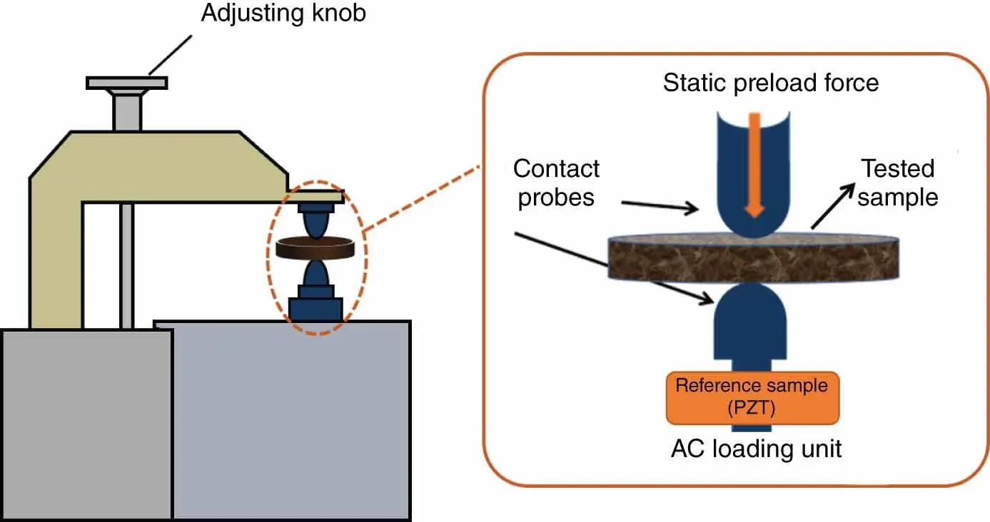
Figure 1.5 Schematic illustration of the components in the force loading system.
Source: Modified from Cain [31].
The main advantage of the Berlincourt method lies in its simplicity. However, due to its simplicity, anyone can design their own measurement systems and no uniform standard about this method were established. We have found various commercial systems with different measurement performance. Though it is still reliable to compare the results measured in the same apparatus, large variabilities exist in the test results from different measurement systems. There are several factors controlling the accuracy and reliability of the results associated with the Berlincourt method. This issue might be briefly introduced by taking, for example, the magnitude and frequency of the applied AC load force. The magnitude of the force does not make much difference as long as if the piezoelectric sample behaves linearly within the stress range. Nonetheless, the increased magnitude of the force is expected to generate a larger charge signal, which helps increase the signal to noise ratio. It is thus better to set the force to at high levels as long as it can still keep the piezoelectric operating in the linear regime. For a typical Berlincourt type instrument, the frequency of the stimulus force usually ranges from 10 Hz to 1 kHz. This range is governed by both the charge measurement system (for the lower limit) and the force loading system (for the upper limit). The frequency for the mechanical or electrical resonance should be avoided in case of the corresponding measurement anomalies. Thus, some specific frequencies are not used in some countries, such as 97 Hz in the United Kingdom and 110 Hz in the United States. The frequency response also varies in different materials, which can result in a frequency dependent gain issue. At the low frequency range, the measured d 33for “soft” piezoelectric materials usually show a pronounced downturn behavior with increasing frequency. This can be attributed to the inhibited domain movement induced by the increasing frequencies, which is depicted by the Rayleigh law. In contrast, the measured d 33for “hard” piezoelectric materials often appears to increase linearly with the frequency as the domain wall motion is not dominant in the low frequency range. This latter behavior is tentatively assumed to be influenced by the proximity to resonance peaks in the kHz region.
In summary, the quasi‐static method is very simple and straightforward. If the relative magnitudes of the charge output and the applied small oscillating force can be measured, one can easily read d 33value by reference to a sample with a known and certificated piezoelectric coefficient.
1.5.2 Measurement of Converse Piezoelectric Coefficient by Laser Interferometer
The displacement of piezoelectric materials under an electric field is concerned as piezoelectric materials usually serve as actuators. However, the displacement is too small to be easily measured in a routine method. With very high resolution and no need for calibration on the length scale, optical interferometry provides the chance for the precise measurement of small displacements within units of nanometer [31–35]. Besides, optical interferometry can achieve the measurement without mechanical contact. Interferometry techniques for the detection of strains have been developed for nearly 50 years. However, at present, this method is still mainly used in research laboratories due to its high price and the need of vibration insulation system.
Piezoelectric coefficients can be measured using single beam, double beam, and heterodyne laser interferometers. For simplicity, the principle for the case based on a single beam laser interferometer is mainly discussed here.
Figure 1.6depicts the schematic diagram of a Michelson interferometer. When a monochromatic light of wavelength λ interferes with a reference beam, the interference light intensity can be described as follows:
(1.17) 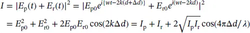
where I pand I rare the intensities of the probing and reference beams, respectively, Δ d is the optical path‐length difference between the two beams, and k = 2π/ λ is the wave number. Actually, the abovementioned relation can be converted into the formula with the parameters, the maximum and minimum interference light intensities I maxand I min, which can be measured by a photo‐detector.
(1.18) 
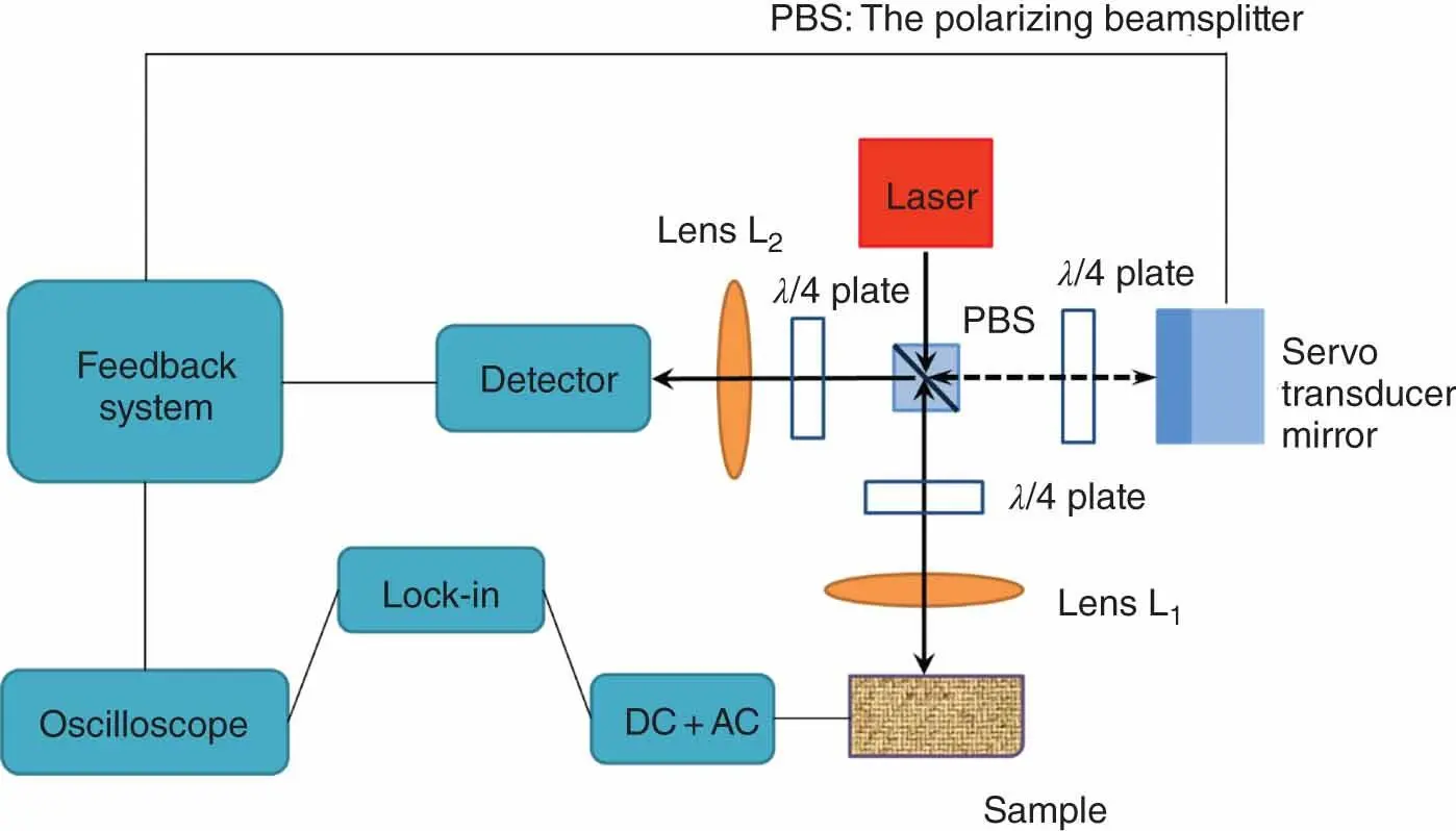
Figure 1.6 Schematic diagram of Michelson interferometer for the measurement of displacement.
In a photodetector, the corresponding photodiode output is determined by the light intensity related to the optical path‐length Δ d , which is directly related with the sample displacement. An amplified output voltage signal corresponding to the displacement can be obtained, which is usually monitored by an oscilloscope. A definite relationship exists between the voltage output and the displacement. According to the relationship, interferometer sensitivity can be actually set to a specific value, say, 10 nm/V. The changes of the sample dimension are induced by the connection and the disconnection of voltage to the sample. The dimension changes by the identical applied voltage are measured multiple times. The averaged measured value and the connected voltage are used to calculate the piezoelectric charge constant d 33, which is governed by the following equation:
Читать дальшеИнтервал:
Закладка:
Похожие книги на «Lead-Free Piezoelectric Materials»
Представляем Вашему вниманию похожие книги на «Lead-Free Piezoelectric Materials» списком для выбора. Мы отобрали схожую по названию и смыслу литературу в надежде предоставить читателям больше вариантов отыскать новые, интересные, ещё непрочитанные произведения.


Обсуждение, отзывы о книге «Lead-Free Piezoelectric Materials» и просто собственные мнения читателей. Оставьте ваши комментарии, напишите, что Вы думаете о произведении, его смысле или главных героях. Укажите что конкретно понравилось, а что нет, и почему Вы так считаете.