Jing-Feng Li - Lead-Free Piezoelectric Materials
Здесь есть возможность читать онлайн «Jing-Feng Li - Lead-Free Piezoelectric Materials» — ознакомительный отрывок электронной книги совершенно бесплатно, а после прочтения отрывка купить полную версию. В некоторых случаях можно слушать аудио, скачать через торрент в формате fb2 и присутствует краткое содержание. Жанр: unrecognised, на английском языке. Описание произведения, (предисловие) а так же отзывы посетителей доступны на портале библиотеки ЛибКат.
- Название:Lead-Free Piezoelectric Materials
- Автор:
- Жанр:
- Год:неизвестен
- ISBN:нет данных
- Рейтинг книги:5 / 5. Голосов: 1
-
Избранное:Добавить в избранное
- Отзывы:
-
Ваша оценка:
Lead-Free Piezoelectric Materials: краткое содержание, описание и аннотация
Предлагаем к чтению аннотацию, описание, краткое содержание или предисловие (зависит от того, что написал сам автор книги «Lead-Free Piezoelectric Materials»). Если вы не нашли необходимую информацию о книге — напишите в комментариях, мы постараемся отыскать её.
Lead-Free Piezoelectric Materials
Lead-Free Piezoelectric Materials
Lead-Free Piezoelectric Materials — читать онлайн ознакомительный отрывок
Ниже представлен текст книги, разбитый по страницам. Система сохранения места последней прочитанной страницы, позволяет с удобством читать онлайн бесплатно книгу «Lead-Free Piezoelectric Materials», без необходимости каждый раз заново искать на чём Вы остановились. Поставьте закладку, и сможете в любой момент перейти на страницу, на которой закончили чтение.
Интервал:
Закладка:
(1.19) 
where U is the applied voltage and Δ l is the change of length determined by multiplying the voltage output of the interferometer and its sensitivity.
Single Beam Michelson interferometers are widely used by different research groups to measure piezoelectric and electrostrictive strains. It should be noted that there are various factors, including sample shape and optical alignment, which can affect the measurement validity and accuracy. To obtain the actual value of the sample dimension change parallel to the laser beam, it should be ensured that only the front surface of a sample can move while the back surface of the sample is fixed, and the sample dimension along the lateral direction can expand and contract freely. Due to these requirements, the specimen shape and dimensions are limited. The bulk sample is usually in the form of a cylinder or a thin plate with a suitable ratio between the lateral dimension and the thickness. If this ratio is very large, the clamping effect and the sample bending effect will become significant. One should not neglect such an impact because the resultant errors can even surpass the longitudinal piezoelectric displacement. When measuring the d 33of a thin film deposited on a very thick substrate, the clamping effect should be concerned as the substrate bonding is usually assumed to be infinitely rigid. The measured d 33is actually the effective converse longitudinal piezoelectric coefficient d 33,eff, which can be determined as follows:
(1.20) 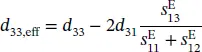
where S ijis the mechanical compliance of the piezoelectric film and d 31is the transverse piezoelectric coefficient.
Proper mounting of the sample is also very important to obtain the actual piezoelectric coefficients. It has been reported that the measured d 33of the same disk specimen of PC5H (Morgan Electro Ceramics) showed different values ranging from 750 to 1250 pC/N when simply changing the way the sample was mounted [34]. The accuracy is also strongly affected by small vibrations or abnormal conditions during the measurement. Thus, the measurements using the laser interferometry should be carried out with great caution and patience, though this type of measurement method is simply based on acquiring the displacement value of the sample surface induced by the corresponding applied voltage.
1.5.3 Resonance and Anti‐resonance Method
Both the quasi‐static method and the laser interferometry method are used for the direct measurements of d 33/ d 31. In contrast to the two aforementioned methods, the resonance and anti‐resonance method, or the frequency method can be applied to determine the complete tensor matrix of the material coefficients [21, 36, 37]. These coefficients can be derived by the raw set of measured parameters including resonant frequencies, density, and sample dimensions. The detailed procedure for the determination of these coefficients can be found in the European standard EN 50324‐2:2002 and the world standard CEI/IEC 60483:1976.
For this method, an accurate impedance analyzer is a crucial requirement as use for the testing of the resonant frequencies f sand antiresonant frequencies f aas well as the free capacitance C Tat 1 kHz. The commercially available lineups of impedance analyzers differ in terms of frequency range and sensitivity. The most regularly used one are, for example, Agilent E4294A and Wayne Kerr 65120B, produced by Agilent and Wayne Kerr, respectively. The other thing to notice is that a set of samples in the forms of a disk, a plate, and a cylinder, which have different vibration modes, should be prepared before the measurements are carried out. Obtaining all the needed sample items from a single bulk material of appropriate size is preferred. The sample dimensions should conform to the world standard CEI/IEC 60483:1976.
Material constants such as piezoelectric coefficient d , dielectric coefficient ε , and elastic coefficient s are anisotropic in general. They are usually described by tensor components written in a simplified matrix form according to the point‐group symmetry of the materials. For piezoelectric ceramics, the complete matrix of the coefficients of electromechanical properties can be written as follows:
(1.21) 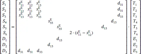
Based on the IEEE standards [22], the requirement of the sample dimensions and the complete matrix of piezoelectric constants can be established as illustrated in Figure 1.7[37].
After acquiring the entry parameters, namely, resonant frequencies, antiresonant frequencies, capacitance, density, and sample dimensions, we can calculate the electromechanical coupling coefficients, according to which elastic coefficients  ,
,  ,
,  ,
,  ,
,  , and
, and  can be derived. As an example, the related formulas for the calculation of the elastic coefficient
  , the piezoelectric charge coefficient d 33, and the piezoelectric voltage coefficient g 33for the longitudinal length mode in the cylinder are deduced based on the IEEE standards as follows:
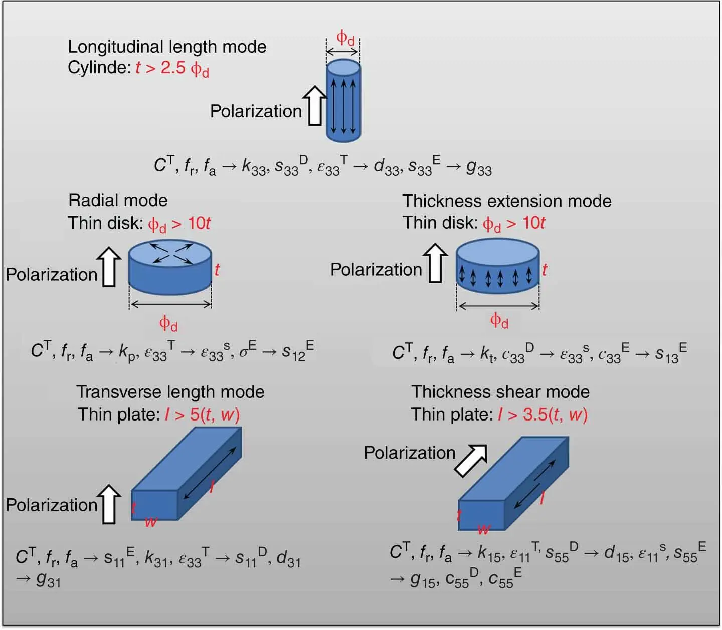
Figure 1.7 Establishing the complete set of material coefficients defined by IEEE standards [37].
Source: Reprinted with permission from Fialka and Benes [37]. Copyright 2013, IEEE.
(1.22) 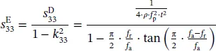
(1.23) 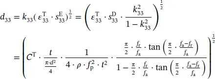
(1.24) 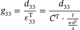
where f ris the resonance frequency, f ais anti‐resonance frequency, and f pis parallel resonant frequency.
The frequency method is advantageous since it can determine the complete matrix of the material coefficients, though a complete set of samples needs to be manufactured. The accuracy of the calculated coefficients depends on the overall measurement accuracy of the initial parameters including resonant frequencies, anti‐resonant frequencies, density, and sample dimensions. Besides, it is worth nothing that the measured samples should comply with a minimum aspect ratio stipulated by the IEEE standards.
Читать дальшеИнтервал:
Закладка:
Похожие книги на «Lead-Free Piezoelectric Materials»
Представляем Вашему вниманию похожие книги на «Lead-Free Piezoelectric Materials» списком для выбора. Мы отобрали схожую по названию и смыслу литературу в надежде предоставить читателям больше вариантов отыскать новые, интересные, ещё непрочитанные произведения.


Обсуждение, отзывы о книге «Lead-Free Piezoelectric Materials» и просто собственные мнения читателей. Оставьте ваши комментарии, напишите, что Вы думаете о произведении, его смысле или главных героях. Укажите что конкретно понравилось, а что нет, и почему Вы так считаете.