(1.119) 
which is plotted for various values of  on the interval
  in Fig. 1.11. It is seen that the gradient at
  rapidly increases with respect to decreasing values of
  .
.
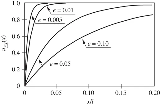
Figure 1.11 The solution  , given by eq. (1.119), in the neighborhood of
  for various values of
  .
.
This is a simple example of boundary layer problems that arise in models of plates, shells and fluid flow. Despite the fact that  is an analytic function, it may require unrealistically high polynomial degrees to obtain a close approximation to the solution when
  is small.
The optimal discretization scheme for problems with boundary layers is discussed in the context of the  ‐version in [85]. The results of analysis indicate that the size of the element at the boundary is proportional to the product of the polynomial degree p and the parameter
  . Specifically, for the problem discussed here, the optimal mesh consists of two elements with the node points located at
  ,
,  ,
,  , where
  with
with  .
.
A practical approach to problems like this is to create an element at the boundary (in higher dimensions a layer of elements) the size of which is controlled by a parameter. The optimal value of that parameter is then selected adaptively.
1.6.2 The exact solution lies in  ,
, 
In this section we consider a special case of the problem stated in eq. (1.103):
(1.120) 
with the data  ,
,  and
and  defined such that the exact solution is
(1.121) 
that is,
(1.122) 
On integrating by parts, we get the following expression which is better suited for numerical evaluation:
(1.123) 
We address the following questions: (a) How does the error in energy norm depend on the parameter α , the mesh Δ and the p ‐distribution p? and (b) How is this error distributed among the elements? Understanding these relationships is necessary for making sound choices of discretization based on a priori information concerning the regularity of the exact solution.
We compute the potential energy of the difference between the exact solution and its linear interpolant for the k th element:

The exact solution for  and its linear interpolant for
  , uniform mesh, are shown in Fig. 1.12.
To obtain the potential energy of the difference between the exact solution and its linear interpolant for the k th element, denoted by  , we need to solve:
(1.124) 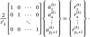
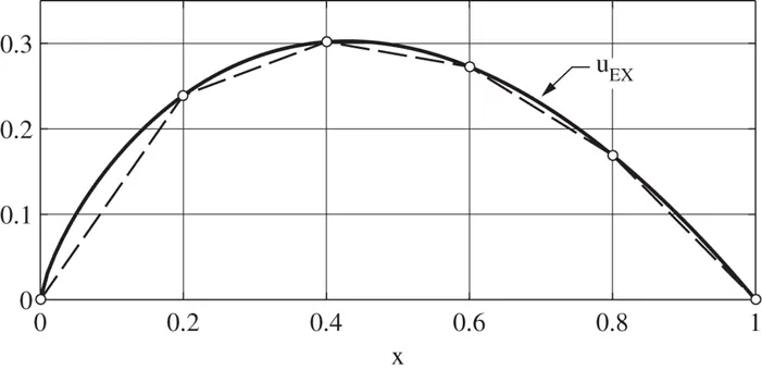
Figure 1.12 The exact solution for  and its linear interpolant for
  , uniform mesh.
Читать дальше


 on the interval
  in Fig. 1.11. It is seen that the gradient at
  rapidly increases with respect to decreasing values of
  .
.
 , given by eq. (1.119), in the neighborhood of
  for various values of
  .
. is an analytic function, it may require unrealistically high polynomial degrees to obtain a close approximation to the solution when
  is small.
 ‐version in [85]. The results of analysis indicate that the size of the element at the boundary is proportional to the product of the polynomial degree p and the parameter
  . Specifically, for the problem discussed here, the optimal mesh consists of two elements with the node points located at
  ,
,  ,
,  , where
  with
with  .
. ,
, 

 ,
,  and
and  defined such that the exact solution is


 and its linear interpolant for
  , uniform mesh, are shown in Fig. 1.12.
 , we need to solve:

 and its linear interpolant for
  , uniform mesh.


