Stephen Rolt - Optical Engineering Science
Здесь есть возможность читать онлайн «Stephen Rolt - Optical Engineering Science» — ознакомительный отрывок электронной книги совершенно бесплатно, а после прочтения отрывка купить полную версию. В некоторых случаях можно слушать аудио, скачать через торрент в формате fb2 и присутствует краткое содержание. Жанр: unrecognised, на английском языке. Описание произведения, (предисловие) а так же отзывы посетителей доступны на портале библиотеки ЛибКат.
- Название:Optical Engineering Science
- Автор:
- Жанр:
- Год:неизвестен
- ISBN:нет данных
- Рейтинг книги:3 / 5. Голосов: 1
-
Избранное:Добавить в избранное
- Отзывы:
-
Ваша оценка:
Optical Engineering Science: краткое содержание, описание и аннотация
Предлагаем к чтению аннотацию, описание, краткое содержание или предисловие (зависит от того, что написал сам автор книги «Optical Engineering Science»). Если вы не нашли необходимую информацию о книге — напишите в комментариях, мы постараемся отыскать её.
Offers a comprehensive review of the topic of optical engineering Covers topics such as optical fibers, waveguides, aspheric surfaces, Zernike polynomials, polarisation, birefringence and more Targets engineering professionals and students Filled with illustrative examples and mathematical equations Written for professional practitioners, optical engineers, optical designers, optical systems engineers and students,
offers an authoritative guide that covers the broad range of optical design and optical metrology topics and their applications.
Optical Engineering Science — читать онлайн ознакомительный отрывок
Ниже представлен текст книги, разбитый по страницам. Система сохранения места последней прочитанной страницы, позволяет с удобством читать онлайн бесплатно книгу «Optical Engineering Science», без необходимости каждый раз заново искать на чём Вы остановились. Поставьте закладку, и сможете в любой момент перейти на страницу, на которой закончили чтение.
Интервал:
Закладка:
(4.15) 
As for the refractive surface we expand Eq. (4.14)using the binomial theorem to give terms of the fourth order in OPD.
(4.16) 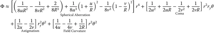
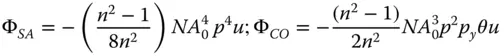
As with the refractive case, four of the five Gauss-Seidel terms are present – spherical aberration, coma, astigmatism, and field curvature. There is also no distortion. As previously, Eq. (4.16)can be simplified considering u , v , and R as dependent variables, as related in Eq. (4.15). We can, once more, express the OPD in terms of u and R alone. Splitting the OPD contributions in Eq. (4.16)into Spherical Aberration (SA), Coma (CO), Astigmatism (AS), and Field Curvature (FC) and with a little algebraic manipulation we have:
(4.17a) 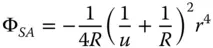
(4.17b) 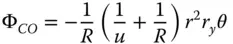
(4.17c) 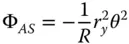
(4.17d) 
Equations (4.17a)– (4.17c)bear some striking similarities with respect to those for the refractive surface. In fact, if one substitutes n = −1 in the corresponding refractive formulae, one obtains expressions similar to those listed above. Thus, in some ways, a mirror behaves as a refractive surface with a refractive index of minus one. Once again, there are aplanatic points where both spherical aberration and coma are zero. This occurs only where both object and image are co-located at the centre of the spherical surface. The apparent absence of field curvature may appear somewhat surprising. However, the Petzval curvature is non-zero, as will be revealed. We can now cast all terms in the form set out in Chapter 3and introduce the Lagrange invariant, which is equal to the product of r 0and θ 0(the maximum field angle):
(4.18a) 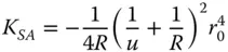
(4.18b) 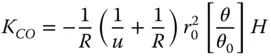
(4.18c) 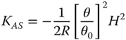
(4.18d) 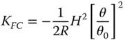
The Petzval curvature is simply given by subtracting twice the K ASterm in Eq. (4.18c)from the field curvature term in Eq. (4.18d). This gives:
(4.19) 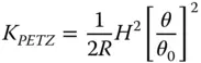
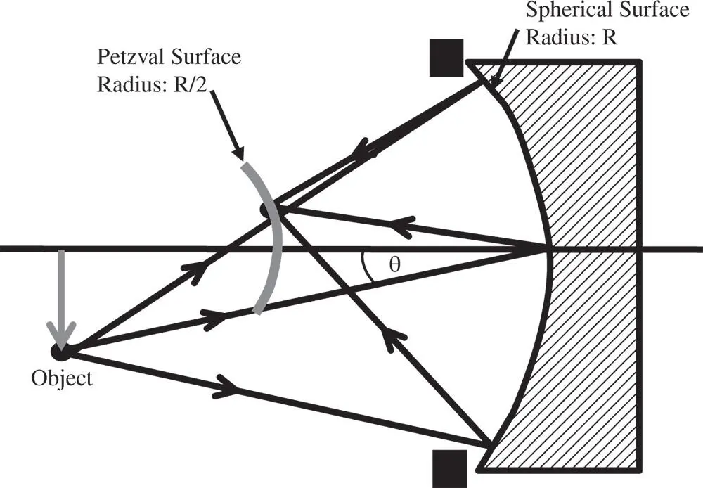
Figure 4.6 Petzval curvature for mirror.
In this instance, the Petzval surface has the same sense as that of the mirror itself. However, the radius of the Petzval surface is actually half that of the original surface. This is illustrated in Figure 4.6.
Calculation of the Petzval sum proceeds more or less as the refractive case. However, there is one important distinction in the case of a mirror system. For a system comprising N mirrors, each successive mirror surface inverts the sense of the wavefront error imparted by the previous mirrors.
(4.20) 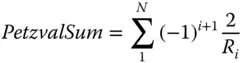
4.4 Refraction Due to Optical Components
4.4.1 Flat Plate
Equations (4.5a)– (4.5d)give the Gauss-Seidel aberration terms for a spherical reflector. However, for a flat surface, where 1/ R = 0, the aberration is non zero.
(4.21) 
If we now make the approximation that r 0/ u ∼ NA 0and express all wavefront errors in terms of the normalised pupil function, we obtain the following expressions.
(4.22) 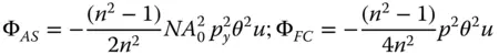
In all expressions, the wavefront error is proportional to the object distance. Equation 4.22only considers refraction at a single surface. For a flat plate whose thickness is vanishingly small, it is clear that refraction at the second (glass-air) boundary will produce a wavefront error that is equal and opposite to that induced at the first surface. Furthermore, it is also clear that the form of wavefront error contribution will be identical to Eq. (4.22), but reversed in sign. For a glass plate of finite thickness, t , the effective object distance, expressed as the object distance in air, will be given by u + t / n . Therefore, the relevant wavefront error contributions at the second surface are given by:

(4.23) 
The total wavefront error is then simply given by the sum of the two contributions. This is expressed in standard format, as below:
(4.24) 
The important conclusion here is that a flat plate will add to system aberration, unless the optical beam is collimated (object at infinite conjugate). This is of great practical significance in microscopy, as a thin flat plate, or ‘cover slip’ is often used to contain a specimen. A standard cover slip has a thickness, typically, of 0.17 mm. Examination of Eq. (4.24)suggests that this cover slip will add significantly to system aberration. In practice, it is the spherical aberration that is of the greatest concern, as θ 0is generally much smaller than NA 0in most practical applications. As a consequence, some microscope objectives are specifically designed for use with cover slips and have built in aberration that compensates for that of the cover slip. Naturally, a microscope objective designed for use with a cover slip will not produce satisfactory imaging when used without a cover slip.
Читать дальшеИнтервал:
Закладка:
Похожие книги на «Optical Engineering Science»
Представляем Вашему вниманию похожие книги на «Optical Engineering Science» списком для выбора. Мы отобрали схожую по названию и смыслу литературу в надежде предоставить читателям больше вариантов отыскать новые, интересные, ещё непрочитанные произведения.


Обсуждение, отзывы о книге «Optical Engineering Science» и просто собственные мнения читателей. Оставьте ваши комментарии, напишите, что Вы думаете о произведении, его смысле или главных героях. Укажите что конкретно понравилось, а что нет, и почему Вы так считаете.