Figure 2.15is a schematic showing the welding of a stationary workpiece [24]. The origin of the coordinate system moves with the heat source at a constant speed V in the negative‐ x direction. Except for the initial and final transients of welding, heat flow in a workpiece of sufficient length is steady, or quasi‐stationary, with respect to the moving heat source. In other words, to an observer moving with the heat source, the temperature distribution and the pool geometry do not change with time. This steady‐state assumption was first used by Rosenthal [25] to simplify the mathematical treatment of heat flow during welding.
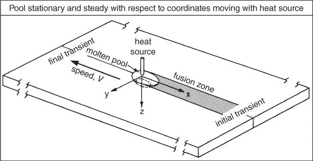
Figure 2.15Coordinate system (x, y, z) moving with heat source.
Source : Kou and Le [24]. © TMS.
2.2.2 Rosenthal's Equations
Rosenthal [25] used the following simplifying assumptions to derive simple analytical equations for heat flow in the workpiece during welding:
1 Steady‐state heat flow
2 Point heat source
3 Negligible heat of fusion
4 Constant thermal properties
5 No heat losses from the workpiece surface
6 No convection in the weld pool
2.2.2.1 Rosenthal's Two‐Dimensional Equation
Figure 2.16is a schematic sketch showing butt welding of thin sheets. Because of the small thickness of the workpiece, temperature variations in the thickness direction are assumed negligible and heat flow becomes two‐dimensional. Rosenthal [25] derived the following equation for two‐dimensional heat flow during the welding of thin sheets of infinite width:
(2.8) 
where
T: temperature
T o: workpiece temperature before welding
k: thermal conductivity
g: workpiece thickness
Q: heat transferred from heat source to workpiece
V: travel speed
α: workpiece thermal diffusivity, namely, k/(ρC), where ρ and C are density and specific heat of workpiece, respectively
K o: modified Bessel function of second kind and zero order [26], as shown in Figure 2.17
r: radial distance from origin, namely, (x 2 + y 2 ) 1/ 2.

Figure 2.16Two‐dimensional heat flow during welding of thin workpiece.
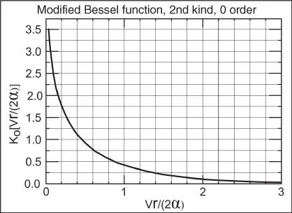
Figure 2.17Modified Bessel function of second kind and zero order.
Equation (2.8) can be used to calculate the temperature T(x, y) at any location in the workpiece ( x, y ) with respect to the moving heat source, for instance, at x = −1 cm and y = 4 cm, as shown in Figure 2.16. The temperatures at other locations along y = 4 cm can also be calculated, and the temperature distribution along y = 4 cm can thus be determined. Table 2.1lists the thermal properties for some common materials. Properties of more materials can be found elsewhere [27].
Table 2.1Thermal properties of some common materials.
| Material |
Thermal diffusivity α (m 2s −1) |
Volume thermal capacity ρC s(Jm −3K −1) |
Thermal conductivity k (Jm −1s −1K −1) |
Melting point (K) |
| Aluminum |
8.5 × 10 −5 |
2.7 × 10 6 |
229.0 |
933 |
| Carbon steel |
9.1 × 10 −6 |
4.5 × 10 6 |
41.0 |
1800 |
| Austenitic stainless steel |
5.3 × 10 −6 |
4.7 × 10 6 |
24.9 |
1773 |
| Ti alloy |
9.0 × 10 −6 |
3.0 × 10 6 |
27.0 |
1923 |
| Copper |
9.6 × 10 −5 |
4.0 × 10 6 |
384.0 |
1336 |
2.2.2.2 Rosenthal's Three‐Dimensional Equation
The analytical solution derived by Rosenthal for three‐dimensional heat flow in a semi‐infinite workpiece during welding, Figure 2.18, is as follows [25]:
(2.9) 
where R is the radial distance from the origin, namely, (x 2 + y 2 + z 2 ) 1/ 2. Equation (2.9) can be used to calculate the steady‐state temperature T(x, y, z) , with respect to the moving heat source, at any location in the workpiece (x, y, z) , for instance, at x = 1 cm, y = 4 cm, and z = 0 cm, as shown in Figure 2.18. The temperatures at other locations along y = 4 cm can also be calculated, and the temperature distribution along y = 4 cm can thus be determined.
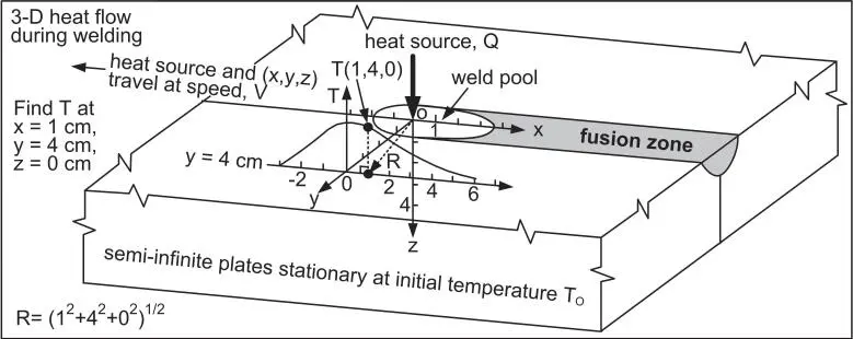
Figure 2.18Three‐dimensional heat flow during welding of semi‐infinite workpiece.
2.2.2.3 Step‐by‐Step Application of Rosenthal's Equations
The procedure for calculating thermal cycles is illustrated as follows. Equation (2.9) for 3D heat flow is used, with V = 2.4 mm/s, Q = 3200 W and T o= 25 °C. Consider the temperature distribution along the straight line of y = 4 cm.
Step 1. Calculate T (1, 4). Let x = 1 cm, y = 4 cm, R = [(1)2 + 42 + 02]1/2.
Step 2. Calculate T from Eq. (2.9) using k and α of the workpiece material (e.g. steel).
Step 3. Repeat Steps 1 and 2 for x = −1, 0, 1, 2, 3, 4, 5 cm.
Step 4. Sketch the temperature distribution T (x, 4, 0).
Step 5. Convert temperature distribution T (x, 4, 0) into thermal cycle T (t) by dividing x by V.
Figure 2.19explains how to convert the calculated temperature distribution in Figure 2.18to a thermal cycle. It is assumed that the workpiece in Figure 2.18is long enough such that, with respect to the moving coordinate system, the temperature field does not change. The T – x plot, i.e. the temperature distribution along the welding direction, can be converted into T – t plot, namely, the thermal cycle , by calculating time t using t = ( x − 0)/ V . For instance, assume the travel speed of the heat source is V = 4 mm/s. At the point x = 2 cm, y = 4 cm, and z = 0 cm, t = (20 mm − 0)/(4 mm/s) = 5 s.
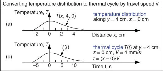
Figure 2.19Converting the calculated temperature distribution in Figure 2.18to thermal cycle, assuming the temperature field is steady with respect to the moving coordinate system.
The shape of the weld pool can be calculated such as at the top surface of the weld pool, i.e. at z = 0 cm. Let T Lbe the liquidus temperature of the workpiece material, e.g. 1530 °C for steel. The liquidus temperature of an alloy is equivalent to the melting point of pure metal T m, above which the workpiece material is melted completely. The procedure for calculating pool shape is illustrated using Eq. (2.9) for 3D heat flow and V = 2.4 mm/s, Q = 3200 W and T o= 25 °C.
Читать дальше
