Step 1. Let T = T L in Eq. (2.9). Calculate R at x = 0 cm and z = 0 cm from Eq. (2.9) by substituting into the equation the values of T o , V, Q, and the physical properties of the workpiece materials (e.g. steel) k and α.
Step 2. Find the value of y from R = (02 + y 2 + 02)1/2.
Step 3. Repeat steps 1 and 2 for x = 1 cm, 2 cm, etc. Use the calculated y values to construct the pool shape at the workpiece surface.
Let T Hbe the temperature at which solid‐state phase transformation occurs (e.g. 780 °C). The shape of the HAZ can be calculated, such as at the top surface of the weld pool, i.e. at z = 0 cm, following the same procedure for calculating the pool shape except that T = T Hin Step 1. The distance in y ‐direction between the weld pool shape (isotherm T L) and the HAZ shape (isotherm T H) is the width of the HAZ.
Adams [28] derived the following equations for calculating the peak temperature T pat the workpiece surface ( z = 0) at a distance Y away from the fusion line (measured along the normal direction):
(2.10) 
for two‐dimensional heat flow and
(2.11) 
for three‐dimensional heat flow. Several other analytical solutions have also been derived for two‐dimensional [29–34] and three‐dimensional [31,35–37] welding heat flow.
2.3 Effect of Welding Conditions
Results of heat flow calculated by Rosenthal's 3D equation are shown in Figures 2.20and 2.21. They show the calculated thermal cycles and temperature distributions at the top surface ( z = 0) of a thick plate of 1018 steel for two different sets of heat input and welding speed. The pool boundary is assumed to be at the liquidus temperature T L= 1530 °C. The solid‐state transformation temperature responsible for the formation of the HAZ at T H= 780 °C. The eutectoid temperature 727 °C of the binary Fe‐C phase diagram might have been a better choice for 1018 steel. However, since the isotherm at 780 °C has already been calculated, it will be taken as T Has an approximation just for the purpose of illustration.
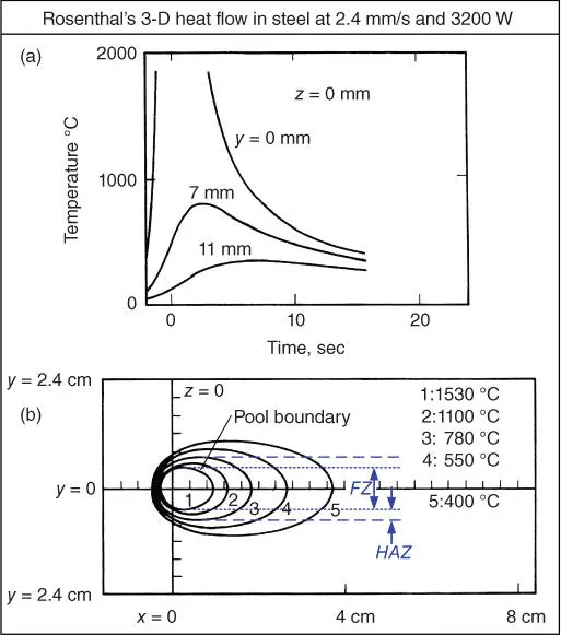
Figure 2.20Calculated Rosenthal's three‐dimensional heat flow in 1018 steel: (a) thermal cycles; (b) isotherms. Welding speed: 2.4 mm/s; heat input: 3200 W; material: 1018 steel; liquidus temperature: 1530 °C; solid‐state transformation temperature: 780 °C.
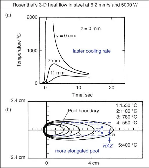
Figure 2.21Similar to Figure 2.20but with faster welding speed of 6.2 mm/s and higher heat input of 5000 W, resulting in faster cooling rate and more elongated weld pool.
As can be seen in Figures 2.20a and 2.21a, the peak temperature of the thermal cycle at the centerline of the weld surface (i.e., at y = z = 0) is infinite. This error is caused by the singularity problem in Rosenthal's equations, that is, caused by the assumption of a point heat source at x = y = z = 0 (the origin of the coordinate system). Thus, near the center of the heat source (the origin), Rosenthal's equations are not reliable. Away from it, however, they can be more accurate. Because of their simplicity, Rosenthal's equations have been used despite the error.
In Figure 2.20 Q = 3200 W and V = 2.4 mm/s, and the Q/V ratio is 1333 J/mm. At the top surface of the workpiece, the weld pool is 9.5 mm wide and 12 mm long, and the length/width ratio is 1.26. In Figure 2.21the power input is increased to Q = 5000 W and the travel speed increased to V = 6.2 mm/s. The Q/V ratio is 806 J/mm. At the top surface of the workpiece, the weld pool is 9.0 mm wide and 16 mm long, and the length/width ratio is 1.78.
Thus, as shown by Rosenthal's 3D equation, the weld pool becomes more elongated as Q and V are both increased. As shown in Figure 2.22, the pool shape in GTAW of a Ni‐base alloy IN718 does become more elongated when Q and V are both doubled [38]. In fact, the weld pool becomes teardrop‐shaped at higher Q and V . Figure 2.23shows the end of a teardrop‐shaped weld pool in GTAW of 309 stainless steel, which was revealed by Kou and Le by quenching the weld pool during welding [39]. Although Rosenthal's equation can correctly predict that the weld pool becomes more elongated at higher Q and V , it cannot calculate a teardrop‐shaped weld pool because it neglects, among other things, heat of fusion and the presence of the liquid phase. A very sharp end of the weld pool like that in Figure 2.22or 2.23is likely caused by undercooling at high travel speed (i.e. high cooling rate).
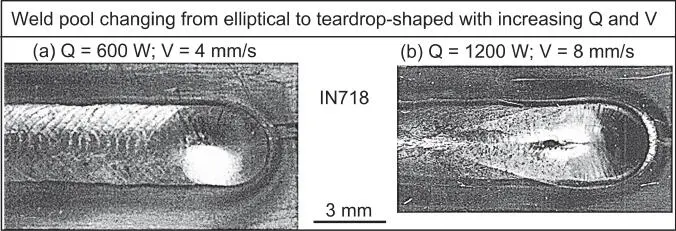
Figure 2.22Weld pool shapes in GTAW of IN718 sheets.
Source : Hunziker, Dye, and Reed [38]. © Elsevier.
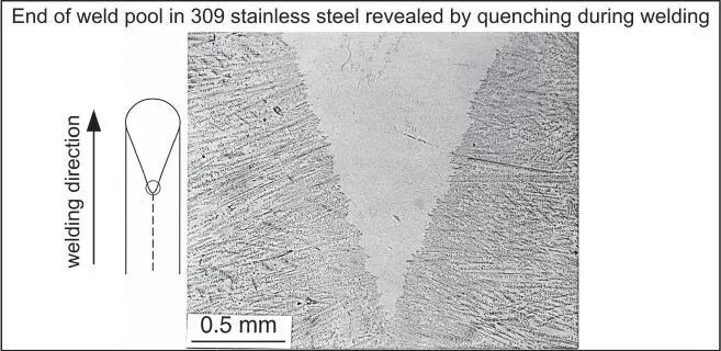
Figure 2.23Sharp pool end in GTAW of 309 stainless steel revealed by ice quenching during welding.
Source : Kou and Le [39]. © TMS.
The calculated results of Rosenthal's equation in Figures 2.20and 2.21show that the cooling rate is higher at a lower Q/V ratio. The thermal cycle at the centerline (y = 0 mm) of the fusion zone is steeper (i.e. higher cooling rate) in Figure 2.21, where Q/V = 806 J/mm, than in Figure 2.20, where Q/V = 1333 J/mm. Lee et al. [40] measured the cooling rate in GTAW of 2024 aluminum by sticking a thermocouple into the weld pool. They showed that decreasing Q/V increased the cooling rate (the slope). Kihara et al. [41] showed that the cooling rate increased with decreasing Q/V and preheating. Liu et al. [42] showed that the cooling rate in electroslag welding (ESW), which is known to have a very high Q/V , is much smaller than that in arc welding. Thus, the prediction of a higher cooling rate at a lower Q/V based on Rosenthal's equation is consistent with experimental results.
Kihara et al. [41] showed that the cooling rate increases with the thickness of the workpiece. This is because a thicker workpiece acts as a better heat sink to cool the weld down. Inagaki and Sekiguchi [43] showed that, under the same heat input and plate thickness, the cooling time is shorter for fillet welding (Figure 1.6d) than for bead‐on‐plate welding because of the greater heat sink effect in the former.
Many computer models have been developed to study 2D heat flow [44–49] and 3D heat flow [24, 50–61] during welding. Kou and Le [24] developed a 3D (x, y, z) finite‐difference computer model to study heat flow and solidification in welding. All Rosenthal's assumptions were dropped. Figure 2.24shows the calculated results of Kou and Le [24] for the GTAW of 3.2‐mm‐thick sheets of 6061 aluminum alloy. The agreement with observed fusion boundaries and thermal cycles is good.
Читать дальше
