Sindo Kou - Welding Metallurgy
Здесь есть возможность читать онлайн «Sindo Kou - Welding Metallurgy» — ознакомительный отрывок электронной книги совершенно бесплатно, а после прочтения отрывка купить полную версию. В некоторых случаях можно слушать аудио, скачать через торрент в формате fb2 и присутствует краткое содержание. Жанр: unrecognised, на английском языке. Описание произведения, (предисловие) а так же отзывы посетителей доступны на портале библиотеки ЛибКат.
- Название:Welding Metallurgy
- Автор:
- Жанр:
- Год:неизвестен
- ISBN:нет данных
- Рейтинг книги:4 / 5. Голосов: 1
-
Избранное:Добавить в избранное
- Отзывы:
-
Ваша оценка:
Welding Metallurgy: краткое содержание, описание и аннотация
Предлагаем к чтению аннотацию, описание, краткое содержание или предисловие (зависит от того, что написал сам автор книги «Welding Metallurgy»). Если вы не нашли необходимую информацию о книге — напишите в комментариях, мы постараемся отыскать её.
The new edition includes new theories/methods of Kou and coworkers regarding:
· Predicting the effect of filler metals on liquation cracking
· An index and analytical equations for predicting susceptibility to solidification cracking
· A test for susceptibility to solidification cracking and filler-metal effect
· Liquid-metal quenching during welding
· Mechanisms of resistance of stainless steels to solidification cracking and ductility-dip cracking
· Mechanisms of macrosegregation
· Mechanisms of spatter of aluminum and magnesium filler metals,
· Liquation and cracking in dissimilar-metal friction stir welding,
· Flow-induced deformation and oscillation of weld-pool surface and ripple formation
· Multicomponent/multiphase diffusion bonding
Dr. Kou’s
has been used the world over as an indispensable resource for students, researchers, and engineers alike. This new
is no exception.
Welding Metallurgy — читать онлайн ознакомительный отрывок
Ниже представлен текст книги, разбитый по страницам. Система сохранения места последней прочитанной страницы, позволяет с удобством читать онлайн бесплатно книгу «Welding Metallurgy», без необходимости каждый раз заново искать на чём Вы остановились. Поставьте закладку, и сможете в любой момент перейти на страницу, на которой закончили чтение.
Интервал:
Закладка:
5 11.5 Experimental results show that in EBW the penetration depth of the weld decreases as the welding speed increases. Explain why. Under the same power and welding speed, do you expect a much greater penetration depth in aluminum or steel, and why?
6 11.6 How does the working distance in EBW affect the depth–width ratio of the resultant weld?
7 11.7 Consider EBW in the presence of a gas environment. Under the same power and welding speed, rank and explain the weld penetration for Ar, He, and air. The specific gravities of Ar, He, and air with respect to air are 1.38, 0.137, and 1, respectively, at 1 atm, 0 °C.
8 11.8 Which arc welding process could have been used for joining the edge weld of thin‐gauge steel shown in Figure P1.8, and why? Figure P1.8Edge weld of thin‐gauge steel.
9 11.9 Two 15‐cm‐thick steel plates were joined together in a single pass, as shown in Figure P1.9. Which welding process could have been used, and why? Figure P1.9Steel plates were joined together in a single pass.
10 11.10 Consider the four typical welding positions. (a) Which position is the easiest in butt welding of plates? (b) Which position is the hardest in butt welding of plates? (c) In butt welding of two steel pipes in the construction of a long‐distance oil pipeline, which welding positions are involved?
11 11.11 Electrodes exposed to air must be baked at 250 °C for 30 minutes to drive out moisture before welding. (a) Which type of electrodes does this procedure apply to? (b) Why?
12 11.12 It was reported that the first covered electrode for SMAW, developed by A. O. Smith Corporation in Milwaukee, was a steel wire spirally wrapped with paper soaked in liquid sodium silicate, a binder, and then baked. It produced an effective gas shield to protect the liquid steel and improved the weld‐metal ductility significantly. What type of electrode covering was this?
13 11.13 Decomposition in air starts at about 545 °C for CaCO3, 325 °C for MgCO3, and 220–250 °C for organic gas formers. (a) If a covered electrode needs to be baked before welding, why should it be kept below a maximum baking temperature? (b) Which material should be baked at a maximum of 150 °C for an electrode covering? (c) What about at 300 °C? (d) What about 450 °C?
14 11.14 Consider butt welding of two horizontal pipes in the circumferential direction by SAW, as shown in Figure P1.14. Suppose the pipe wall is thick, so the molten weld pool and slag are large and long and tend to run away. (a) Suppose the electrode is at position A. Sketch the molten weld pool. (b) Should the electrode position be changed to B or C in order to minimize the problem? Hint: Moving the workpiece in one direction under a stationary arc is equivalent to moving the arc in the opposite direction over a stationary workpiece. Figure P1.14SAW butt welding of two horizontal pipes.
2 Heat Flow in Welding
Heat flow affects the microstructure and properties of the resultant weld and the residual stresses and distortion in the welded workpiece. This chapter deals with the heat source, heat flow in the workpiece, effect of welding conditions on heat flow, computer simulation of heat flow, and simulation of thermal cycles in small specimens by Gleeble.
It draws frequently on the work conducted at UW‐Madison, including measurements of the power inputs in gas‐tungsten arc welding (GTAW) and gas–metal arc welding (GMAW), measurements of the power‐density distribution in a gas−tungsten arc, and 3D computer simulation of heat flow in welding, which was subsequently extended to 3D computer simulation of heat and fluid flow in the weld pool.
2.1 Heat Source
2.1.1 Heat Source Efficiency
A significant portion of the nominal power provided for welding can be lost to the surroundings, as illustrated in Figure 2.1using GTAW as an example. The surrounding air, the water‐cooled contact tube, and the backing plate can all pick up a certain portion of the nominal power.
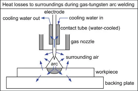
Figure 2.1Heat losses to the surroundings in GTAW. A portion of the nominal power Q (= current × voltage) generated is lost to the surroundings as shown.
2.1.1.1 Definition
The heat source efficiency η is defined as
(2.1) 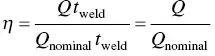
where Q is the rate of heat transfer from the heat source to the workpiece, Q nominalthe nominal power of the heat source, and t weldthe welding time. A portion of the power provided by the heat source is transferred to the workpiece and the remaining portion is lost to the surroundings. Consequently, η < 1. If the heat source efficiency η is known, the heat transfer rate to the workpiece, Q , can be easily determined from Eq. (2.1).
In arc welding with a constant voltage E and a constant current I , the arc efficiency can be expressed as
(2.2) 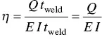
Equation (2.2) can also be applied to electron beam welding (EBW), where η is the heat source efficiency. In laser beam welding (LBW), Q nominalin Eq. (2.1) is the power of the laser beam, for instance, 2500 W.
It should be noted that in welding the term heat input often refers to Q nominal(or EI in the case of arc welding) and the term heat input per unit length of weld often refers to the ratio Q nominal/ V (or EI/V in the case of arc welding) where V is the travel speed of the heat source.
2.1.1.2 Measurements
The heat source efficiency can be measured with a calorimeter. The heat transferred from the heat source to the workpiece is in turn transferred from the workpiece to the calorimeter, which can be determined as follows.
Kou and coworkers [1, 2] used simple tubular calorimeters to determine the arc efficiency in GTAW of aluminum, as shown in Figure 2.2a. The calorimeter can be a tube if the workpiece is a tube. It can also be a rectangular box if the workpiece is a plate, which can be the cover of the box and an O‐ring can be provided between the cover and the rest of the box to keep water from leaking out of the box. The temperature rise in the cooling water ( T out− T in) can be measured using thermocouples or thermistors. Heat transfer from the workpiece to the calorimeter is as follows [1–3]:
(2.3) 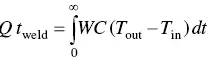
where W is the mass flow rate of water, C the specific heat of water, T outthe outlet water temperature, T inthe inlet water temperature, t is time, and t weldis welding time. The integral in Figure 2.2a corresponds to the shaded area in Figure 2.2b. The arc efficiency η can be determined from Eqs. (2.2) and (2.3).
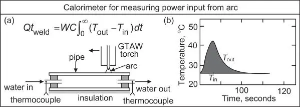
Figure 2.2Measurement of arc efficiency in GTAW: (a) calorimeter; (b) rise in cooling water temperature as a function of time. WC is taken as constant because W is constant and C essentially constant.
Читать дальшеИнтервал:
Закладка:
Похожие книги на «Welding Metallurgy»
Представляем Вашему вниманию похожие книги на «Welding Metallurgy» списком для выбора. Мы отобрали схожую по названию и смыслу литературу в надежде предоставить читателям больше вариантов отыскать новые, интересные, ещё непрочитанные произведения.


Обсуждение, отзывы о книге «Welding Metallurgy» и просто собственные мнения читателей. Оставьте ваши комментарии, напишите, что Вы думаете о произведении, его смысле или главных героях. Укажите что конкретно понравилось, а что нет, и почему Вы так считаете.