Sindo Kou - Welding Metallurgy
Здесь есть возможность читать онлайн «Sindo Kou - Welding Metallurgy» — ознакомительный отрывок электронной книги совершенно бесплатно, а после прочтения отрывка купить полную версию. В некоторых случаях можно слушать аудио, скачать через торрент в формате fb2 и присутствует краткое содержание. Жанр: unrecognised, на английском языке. Описание произведения, (предисловие) а так же отзывы посетителей доступны на портале библиотеки ЛибКат.
- Название:Welding Metallurgy
- Автор:
- Жанр:
- Год:неизвестен
- ISBN:нет данных
- Рейтинг книги:4 / 5. Голосов: 1
-
Избранное:Добавить в избранное
- Отзывы:
-
Ваша оценка:
Welding Metallurgy: краткое содержание, описание и аннотация
Предлагаем к чтению аннотацию, описание, краткое содержание или предисловие (зависит от того, что написал сам автор книги «Welding Metallurgy»). Если вы не нашли необходимую информацию о книге — напишите в комментариях, мы постараемся отыскать её.
The new edition includes new theories/methods of Kou and coworkers regarding:
· Predicting the effect of filler metals on liquation cracking
· An index and analytical equations for predicting susceptibility to solidification cracking
· A test for susceptibility to solidification cracking and filler-metal effect
· Liquid-metal quenching during welding
· Mechanisms of resistance of stainless steels to solidification cracking and ductility-dip cracking
· Mechanisms of macrosegregation
· Mechanisms of spatter of aluminum and magnesium filler metals,
· Liquation and cracking in dissimilar-metal friction stir welding,
· Flow-induced deformation and oscillation of weld-pool surface and ripple formation
· Multicomponent/multiphase diffusion bonding
Dr. Kou’s
has been used the world over as an indispensable resource for students, researchers, and engineers alike. This new
is no exception.
Welding Metallurgy — читать онлайн ознакомительный отрывок
Ниже представлен текст книги, разбитый по страницам. Система сохранения места последней прочитанной страницы, позволяет с удобством читать онлайн бесплатно книгу «Welding Metallurgy», без необходимости каждый раз заново искать на чём Вы остановились. Поставьте закладку, и сможете в любой момент перейти на страницу, на которой закончили чтение.
Интервал:
Закладка:
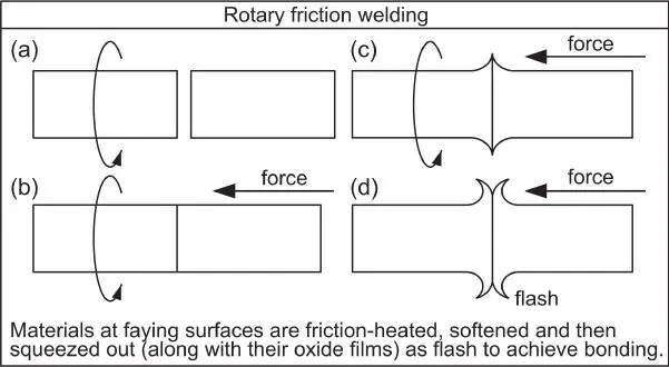
Figure 1.38Schematic illustration of rotary friction welding: (a) first piece (axisymmetric) rotating; (b) second piece brought into contact with first piece to cause friction heating; (c) second piece forced against first piece to squeeze materials and oxide films out of the joint area as flash; (d) rotation stopped.
There are two variations of RFW. In direct‐drive (or continuous‐drive) friction welding, the rotating member of the workpiece is directly attached to a motor drive unit to rotate at a constant speed while rubbing against the nonrotating member. The motor is stopped after a predetermined heating time or until a preset axial shortening (called upsetting) occurs. The drive is then disengaged to allow the rotating member to be braked to a stop. In inertia friction welding, on the other hand, the rotating member of the workpiece is connected to a flywheel driven by a motor. After the flywheel is accelerated to the predetermined speed, it is disengaged from the motor. The nonrotating is then pushed against the rotating one until the rotation stops.
There are at least four advantages of RFW:
1 The HAZ is very narrow because the friction is localized at the interface.
2 Dissimilar metals can be welded because there is no melting to cause massive brittle intermetallic compounds to form.
3 Welded joints produced by this process are often as strong as the base metal.
4 The power requirement is low.
There are three disadvantages to friction welding:
1 In general, at least one member of the workpiece must have an axis of symmetry and be capable of being rotated about that axis.
2 Careful preparation and alignment of the members is required to ensure uniform rubbing and heating, particularly with large diameters.
3 Equipment cost is high.
Figure 1.39shows linear friction welding (LFW). It was developed to use linear reciprocating motion for non‐round parts. One part is set in linear reciprocating motion and the other part, stationary, is forced against it. Again, friction at the interface generates heat to plasticize the material near the faying surfaces, and the applied force squeezes it out as flash (not shown). As an example, the amplitude of vibration is 1–3 mm, the frequency 25–125 Hz, and the axial force 150 kN. By reducing the amplitude of reciprocating motion at the end of the weld cycle to terminate the friction phase, instead of slowing down the frequency, the two parts can be accurately aligned with respect to each other. A well‐known application of linear FSW is the joining of aero‐engine compressor blades to compressor disks, to form blisks [29].
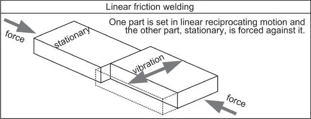
Figure 1.39Linear friction welding in which a stationary member is forced against a reciprocating member to generate frictional heat to plasticize and remove the material and oxide films near the faying surfaces to cause bonding.
1.6.3 Explosion and Magnetic‐Pulse Welding
Figure 1.40illustrates a solid‐state welding process in which a large force is suddenly generated to fast accelerate (e.g. to >500 m/s) one member (called flyer plate) of the workpiece to make it collide with the other member (called the base plate) at an angle (e.g. 15°). As the collision front moves forward fast, the materials near the interface, along with their surface oxide films, are expelled as a jet, allowing the fresh, oxide‐free materials to bond together firmly. At the interface between the two members, the material of the flyer plate moves forward very fast, but the material of the base plate is stationary. The mismatch in the forward moving speed causes a flow instability at the interface, resulting in a wavy interface. The wavy interface is clear if the two materials are similar in strength. However, it may not be as clear if one material is much harder than the other such as steel and Al.
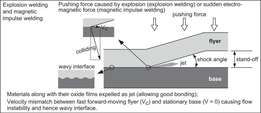
Figure 1.40Schematic illustration of solid‐state joining by making one member (flyer) of the workpiece fast collide with a stationary member (base), such as explosion welding or magnetic impulse welding.
In the explosion welding (EXW) process, the sudden force is caused by an explosive. In the magnetic‐pulse welding (MPW) process, on the other hand, an instant electromagnetic force is generated by a fast discharge of capacitors into a coil (e.g. 500 kA) to cause a high pulsed current (e.g. 500 kA and 15 kHz). The pulsed current produces a high‐density magnetic field, creating an eddy current in one member of the workpiece and a repulsive force to accelerate it to collide with the other member. The high collision velocity (e.g. 500 m/s) causes the two members to be welded together upon impact.
EXW or MPW have two main advantages:
1 Excellent welds can be made between different metals, with hardly any brittle intermetallic compounds.
2 The joint strength can be close to that of the base metal.
They have three main disadvantages:
1 Explosion welding is expensive and requires a special license.
2 Magnetic pulse welding equipment is expensive.
3 Limited to joint designs with overlapping between two members of the workpiece.
1.6.4 Diffusion Welding
Diffusion welding is a joining process in which the main mechanism for joint formation is solid‐state diffusion. It is often called diffusion bonding. Coalescence of the faying surfaces is accomplished by applying pressure at elevated temperature as illustrated in Figure 1.41[1]. The faying surfaces need to be machined very smooth and clean. However, microscopically the faying surfaces are still rough and need to be brought into close contact under pressure at elevated temperature. The elevated temperature softens the materials, allowing close contact under pressure and increasing the diffusion coefficient.
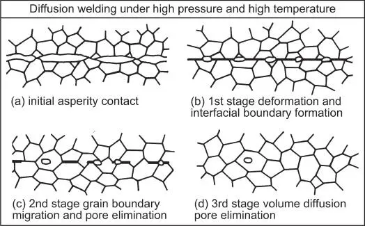
Figure 1.41Diffusion welding between an upper piece and a lower piece showing the microstructure in the vertical cross‐section near the faying surfaces [1].
Source : Welding Handbook, Volume 3, 1980, © American Welding Society.
There are two main advantages of diffusion welding:
1 High‐quality joints can be produced with microstructure and properties close to those of the base metal.
2 Dissimilar metals that are not weldable by fusion welding can be joined.
Disadvantages include the following:
1 High equipment cost and long joining time are often required.
2 Great care is required in preparing the faying surfaces, and the fit‐up of mating parts often need extra care.
Examples
Example 1.1A 1100 Al (commercially pure Al) sheet was welded by GTAW with a 1100 Al filler wire, as shown in Figure E1.1. (a) What is wrong with the weld? (b) Were the filler metal droplets able to enter the weld pool properly? Why or why not? (c) Which polarity of GTAW was used for welding? (d) How can the problem be overcome?
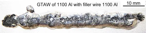
Figure E1.1GTAW process used to weld A 1100 Al sheet with a 1100 Al filler wire.
Читать дальшеИнтервал:
Закладка:
Похожие книги на «Welding Metallurgy»
Представляем Вашему вниманию похожие книги на «Welding Metallurgy» списком для выбора. Мы отобрали схожую по названию и смыслу литературу в надежде предоставить читателям больше вариантов отыскать новые, интересные, ещё непрочитанные произведения.


Обсуждение, отзывы о книге «Welding Metallurgy» и просто собственные мнения читателей. Оставьте ваши комментарии, напишите, что Вы думаете о произведении, его смысле или главных героях. Укажите что конкретно понравилось, а что нет, и почему Вы так считаете.