1.5 Resistance Spot Welding
The resistance spot welding (RSW) process is shown schematically in Figure 1.33. Two overlapping metal parts are squeezed tightly against each other by the tips of two opposing electrodes that are water‐cooled. The resistance to the electric current passing through the electrodes and parts can exist in the form of bulk resistance and contact resistance. The highest resistance usually is at the faying surfaces (represented by Point 4), thus causing local heating and melting at the faying surfaces to form a weld nugget after cooling.
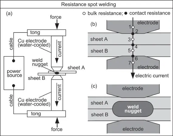
Figure 1.33Resistance spot welding: (a) overview; (b) resistance to electric current; (c) weld nugget.
The electrode clamping force need to be sufficient to keep the liquid in the nugget from being expelled, called expulsion or spitting . The lower density of liquid than solid causes volume expansion upon melting and promotes expulsion. Expulsion can leave insufficient liquid in the nugget to form a continuous solid weld, resulting in large voids and weakening the weld.
The key process variables include the welding current (usually several thousands to tens of thousands of amperes), welding time, clamping force, and electrode shape. The copper electrodes are often alloyed with refractory metals to improve erosion resistance. It is desirable to have a nugget with a diameter about 3.5–4 times the sheet thickness and a height about two‐thirds the combined thickness of the sheets [27]. To reduce erosion, some electrode tips are coated with special materials.
In welding dissimilar metals, e.g., Cu to steel as shown in Figure 1.34, heat balance may need to be considered. The much higher thermal conductivity of Cu than steel may prevents Cu from being melted sufficiently. So, Cu can be thicker and a smaller electrode tip area can be used to increase the current density. Alternatively, an electrode tip with high electrical resistance material such as tungsten or molybdenum can be used.
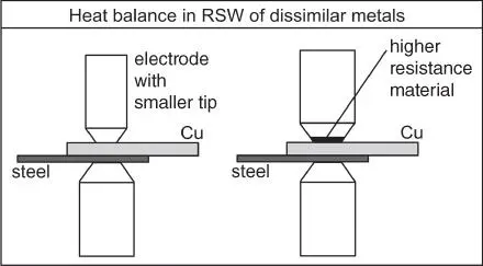
Figure 1.34Resistance spot welding of dissimilar metals with highly different thermal conductivities.
1.6 Solid‐State Welding
1.6.1 Friction Stir Welding
FSW is a solid‐state joining process invented by The Welding Institute in UK in 1991 [28]. As shown in Figure 1.35, the tool typically has a shoulder (which can be flat or slightly concave) and a pin (also called a probe) at its lower end. For welding Al alloys, the tool is made of tool steel, e.g. H13 steel. For butt welding, the length of the pin is slightly less than the thickness of the workpiece. The pin is typically threaded to help push the surrounding material downward, while stirring it, to enhance the mixing action. An example of the tool is shown in Figure 1.35b. It is a H13 steel tool, with a shoulder of 15 mm diameter and a threaded pin of 6.0 mm diameter and 5.4 mm length beyond the shoulder. The shoulder is slightly concave.
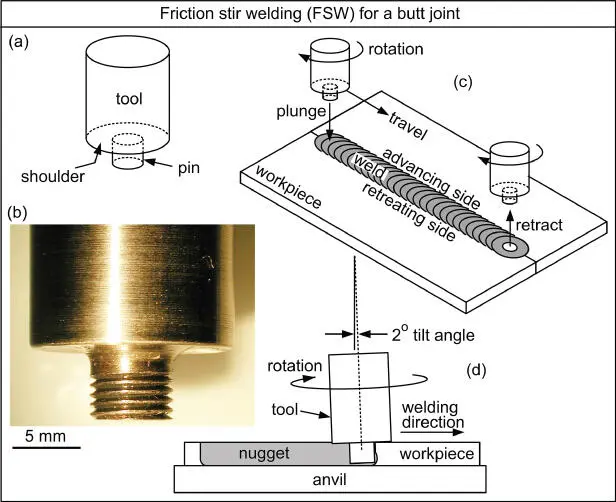
Figure 1.35Friction stir butt welding: (a) tool (b) photo of tool; (c) butt welding; (d) tilting tool forward, usually by about 2°. Tight clamping of the workpiece (not shown) is required during welding.
To keep the workpiece from moving during welding, the workpiece must be clamped down very tightly and supported firmly at the bottom by an anvil. To initiate welding, the rotating tool is plunged into the workpiece until the shoulder is slightly below and rubs the workpiece surface. Friction heat softens the material around the tool. After a brief dwell time, the rotating tool is traversed along the joint. Welding is achieved by plastic flow of frictionally heated material from ahead of the pin to behind it. At the end of the weld, the rotating tool is withdrawn, leaving behind a small crater (or keyhole). The tool is typically tilted forward about 2° during welding. This allows the tool to move forward without shaving the surface of the workpiece and to compress the stirred material under the trailing portion of the shoulder.
Figure 1.36shows the transverse cross‐section of the stir zone and its surroundings. In the stir zone, which is also called the nugget, very fine grains form by dynamic recrystallization. In the thermally affected zone, which is equivalent to the HAZ of an arc weld, no deformation of grains occurs. Between the stir zone and the HAZ, a thermomechanically affected zone may exist, where grains are twisted by the action of tool rotation without dynamic recrystallization.
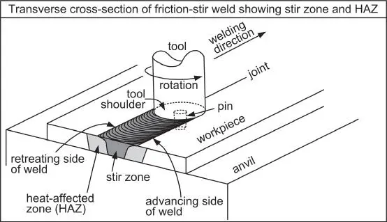
Figure 1.36Stir zone (dynamically recrystallized zone) and HAZ (thermally affected zone) in a friction stir weld. A thermomechanically affected zone may exist between the two, where grains are only twisted but not dynamically recrystallized into very fine grains.
FSW is also suitable for making a lap weld, as illustrated in Figure 1.37. The pin needs to be longer than the thickness of the upper sheet in order to penetrate into the lower sheet to stir it and weld it to the upper sheet. When the process is used to make a spot weld, it is called friction stir spot welding (FSSW). As illustrated in Figure 1.37, in FSSW the rotating tool dwells at one spot after the penetration depth is reached. In friction stir lap welding, however, the rotating tool travels after reaching the desired penetration depth.
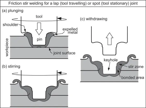
Figure 1.37Friction stir lap or spot welding: (a) plunging rotating tool into upper sheet; (b) dwelling (in spot welding) or traversing (in lap welding) rotating tool after pin tip penetrating into lower sheet and shoulder penetrating upper sheet slightly; (c) retracting rotating tool.
FSW is ideal for welding Al alloys. Joint designs for FSW include butt, lap, T‐, fillet, and corner joints. Mg alloys and Cu alloys are also very weldable by FSW. FSW of steels is much more difficult because the tools need to be very hard and durable. Tools such as W, W─Re, and pyrolytic BN have been used for FSW of steels.
The major advantages of FSW are as follows: (i) solid‐state welding, allowing joining of materials difficult to fusion weld (e.g. 2000 and 7000 series aluminum alloys, which often crack in arc welding); (ii) low distortion; and (iii) excellent mechanical properties due to fine grains in the stir zone. There are some limitations, however: (i) tool wear is a problem in FSW of steels, stainless steels, and titanium alloys; (ii) rigidly clamping of the workpieces is required; (iii) a backing anvil is required; and (iv) a keyhole is left at the end of the weld.
Friction welding is a solid‐state joining process that joins metals by heating two surfaces through mechanically induced rubbing motion and forcing them against each other. Figure 1.38shows rotary friction welding (RFW). First, one member of the workpiece is rotated and the other is stationary. When the appropriate rotational speed is reached, the stationary member is forced against the rotating one to cause friction heating to soften the materials at the faying surfaces. This is the rubbing or friction stage, during which the welding heat is developed. After that, the force is increased significantly to squeeze out the softened materials and their oxide films as flash. This is the upsetting or forging stage, during which weld is further heated, the softened materials and their oxide films are squeezed out as flash to allows fresh, oxide‐free materials to bond together. Under the combined action of heating and forging, a hot plasticized layer is formed between the two workpieces in which material mixing occurs. Excessive upsetting results in too big a flash while insufficient upsetting can cause poor bonding.
Читать дальше
