A. Kayode Coker - Petroleum Refining Design and Applications Handbook
Здесь есть возможность читать онлайн «A. Kayode Coker - Petroleum Refining Design and Applications Handbook» — ознакомительный отрывок электронной книги совершенно бесплатно, а после прочтения отрывка купить полную версию. В некоторых случаях можно слушать аудио, скачать через торрент в формате fb2 и присутствует краткое содержание. Жанр: unrecognised, на английском языке. Описание произведения, (предисловие) а так же отзывы посетителей доступны на портале библиотеки ЛибКат.
- Название:Petroleum Refining Design and Applications Handbook
- Автор:
- Жанр:
- Год:неизвестен
- ISBN:нет данных
- Рейтинг книги:3 / 5. Голосов: 1
-
Избранное:Добавить в избранное
- Отзывы:
-
Ваша оценка:
Petroleum Refining Design and Applications Handbook: краткое содержание, описание и аннотация
Предлагаем к чтению аннотацию, описание, краткое содержание или предисловие (зависит от того, что написал сам автор книги «Petroleum Refining Design and Applications Handbook»). Если вы не нашли необходимую информацию о книге — напишите в комментариях, мы постараемся отыскать её.
Petroleum Refining Design and Applications Handbook — читать онлайн ознакомительный отрывок
Ниже представлен текст книги, разбитый по страницам. Система сохранения места последней прочитанной страницы, позволяет с удобством читать онлайн бесплатно книгу «Petroleum Refining Design and Applications Handbook», без необходимости каждый раз заново искать на чём Вы остановились. Поставьте закладку, и сможете в любой момент перейти на страницу, на которой закончили чтение.
Интервал:
Закладка:
Figure 14.17csummarizes a system for representing components on the flowsheets. The instrument symbols of Table 14.6and Figures 14.18aand b are representative of the types developed by the Instrument Society of America and some companies.
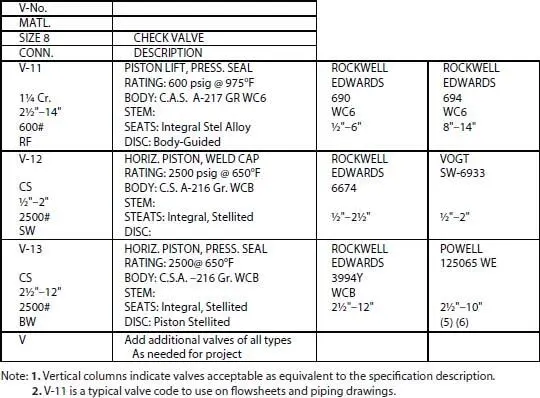
Figure 14.21 Typical valve codes and specifications. By permission, Borden Chemicals and Plastics Operating Ltd. Partnership.
Some other designation systems indicate the recording or indicating function in front of rather than behind the instrument function. For example:
| RTC-1, | Recording Temperature Controller No. 1 |
| VRTC-1, | Control Valve for Recording Temperature Controller No. 1 |
| RFM-6, | Recording Flow Meter No. 6 |
| ORFM-6, | Orifice flanges and plate for Recording Flow Meter No. 6 |
| OTrRFC-1, | Orifice flanges and plate used with Transmitter for recording Flow Controller No. 1 |
| TrRFC-1F, | Flow Transmitter for Recording Flow controller No. 1 |
| IPC-8, | Indicating Pressure Controller No. 8 |
| IFC-6, | Indicating Flow Controller No. 6 |
| IFM-2, | Indicating Flow Meter No. 2 |
| RLC-, | Recording Level Controller |
| RLM-, | Recording Level Meter |
| ILC-, | Indicating Level Controller |
| LC-, | Level Controller |
| PC-, | Pressure Controller |
Control valves carry the same designation as the instrument to which they are connected. Thermocouples carry the same designation as the recorder or indicator to which they are connected. Sequential point numbers are indicated thus (see Table 14.6):
| RTM-6-4, | Thermocouple connected to point No. 4 |
| RTM instrument No. 6. Also see Figure 14.9. |
Additional symbols include:
| PG-6, | Pressure Gage No. 6 connected in the field on some item of equipment. If panel board mounted, it becomes-6B. |
| LTA-1, | Low Temperature Alarm No. 1 |
| HTA-1, | High Temperature Alarm No. 1 |
| LPA-2, | Low Pressure Alarm No. 2 |
| HPA-2, | High Pressure Alarm No. 2 |
| LLA-6, | Low Level Alarm No. 6 |
| HLA-8, | High Level Alarm No. 8 |
| PG-, | Push Button |
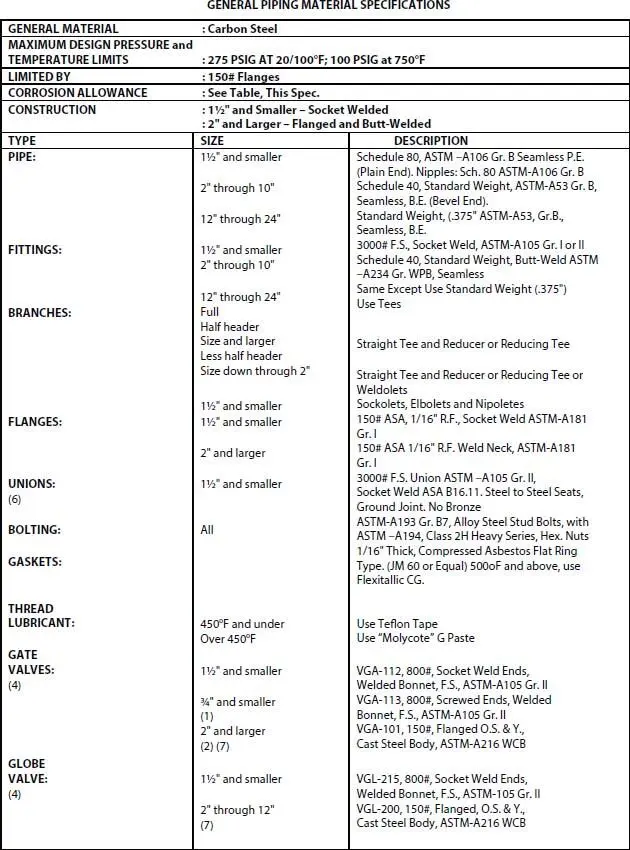
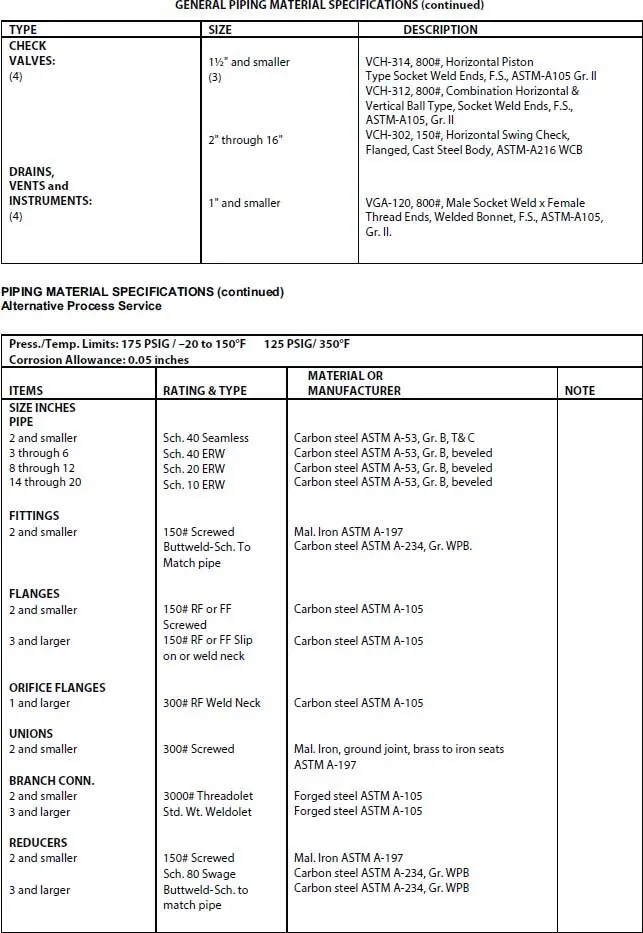
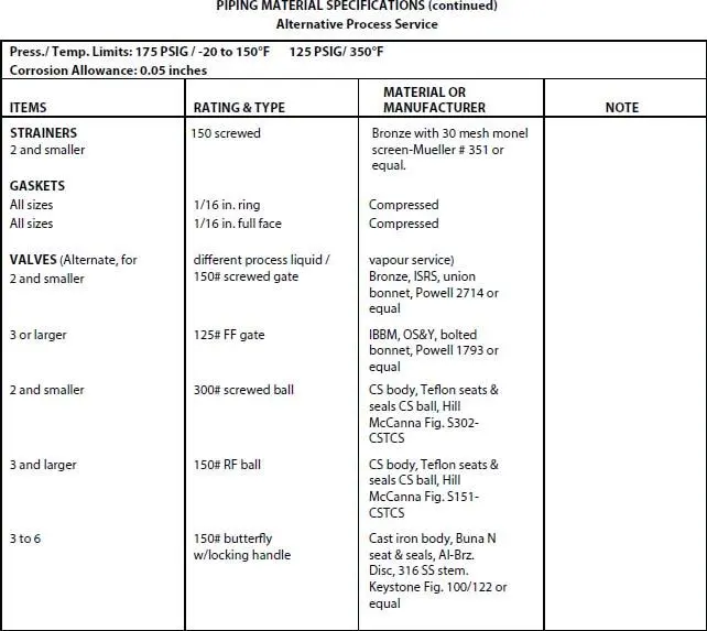
Figure 14.22 Partial presentation of piping materials specifications for a specific process service. By permission, Borden Chemicals and Plastics, Operating Limited Partnership.
Process flowsheets do not normally show companion flanges for valves unless these serve as blinds or for orifice plates. This detail is sometimes shown on the piping flowsheet, but here again the use of detail, which does not contribute to the communication function of the sheets, is avoided. Such detail can be time consuming when considered over the entire set of sheets for a process. Figures 14.7and 14.9are typical of reasonably good presentation without unnecessary detail. Such specifications as heights of a seal leg, locked open valve, or other information not summarized elsewhere must be recorded on the flowsheets.
14.13 Working Schedules
As a direct companion of the completed flowsheet, the line schedule sheet transmits the process and mechanically necessary details for proper interpretation of the piping aspects of the flowsheet (see Figures 14.20a– d). These schedules are initiated by the process engineer to further explain the requirements of the process as shown on the flowsheets. They are often and perhaps usually cooperatively completed by other engineers, particularly the piping, mechanical and instrumentation groups.
Table 14.6 Instrumentation nomenclature--complete general identification.
| Modification of ISA Standards | |||||||||||||||
| First Letter | Second and Third Letters | ||||||||||||||
| Controlling Devices | Measuring Devices | Alarm Devices | |||||||||||||
| * Process Variable or Actuation | Recording | Indicating | Nonindicating (Blind) | Valves | Self-Actuated valve | Safety Valve | Recording | Indicating | Recording | Indicating | Nonindicating (Blind) | Primary Elements | Wells | Glass Devices for Visual Observation | |
| RC | IC | C | CV | V | SV | R | I | RA | IA | A | E | W | G | ||
| Flow | F | FRC | FIC | FV | FR | FI | FRA | FIA | FA | FE | FG | ||||
| Level | L | LRC | LIC | LC | LCV | LV | LR | LI | LRA | LIA | LA | LE | LG | ||
| Pressure | P | PRC | PIC | PC | PCV | PV | PSV | PR | PI | PRA | PIA | PA | PE | ||
| Speed | S | SRC | SIC | SC | SCV | SSV | SR | SI | SRA | SIA | SA | ||||
| Weight | W | WRC | WIC | WR | WI | WRA | WIA | WE | |||||||
| Analysis | A | ARC | AIC | AC | ACV | ASV | AR | AI | ARA | AIA | AA | AE | |||
| Hand | H | HIC | HC | HCV | |||||||||||
| Temperature | T | TRC | TIC | TC | TCV | TV | TSV | TR | TI | TRA | TIA | TA | TE | TW | |
| Special | X | XRC | XIC | XC | XCV | XSV | XR | XI | XRA | XIA | XA | XE |
Note : Blank spaces are impossible or improbable combinations.
Source : By permission from Oriolo D.J., Oil Gas J., Nov. 17, 1958; also see ISA Stds Latest edition.
A schedule similar to Figure 14.20ais used to summarize insulation process code or class, and pressure test information to the erection contractor. The process code is the complete code specification (as a separate fluid process service detailed for each fluid) tabulation for the required piping materials, fittings, valves, gaskets, thread lubricant, etc., for a specific process or utility fluid (see Figures 14.21and 14.22). For example, it identifies the type of gate, globe, plug, check and needle valves to be used in the fluid by specific catalog figure number of a manufacturer or its equivalent. This requires attention to materials of construction, pressure–temperature ratings, and connections (flanged, screwed, weldend), bonnet type, packing, seat type (removable or non removable), stem, and any other details affecting the selection of a valve for the process fluid conditions. It also contains the specifications for pipe, fittings, flanges, unions, couplings, gaskets, thread compound, bolting, and any special materials needed to properly complete the piping requirements.
Читать дальшеИнтервал:
Закладка:
Похожие книги на «Petroleum Refining Design and Applications Handbook»
Представляем Вашему вниманию похожие книги на «Petroleum Refining Design and Applications Handbook» списком для выбора. Мы отобрали схожую по названию и смыслу литературу в надежде предоставить читателям больше вариантов отыскать новые, интересные, ещё непрочитанные произведения.


Обсуждение, отзывы о книге «Petroleum Refining Design and Applications Handbook» и просто собственные мнения читателей. Оставьте ваши комментарии, напишите, что Вы думаете о произведении, его смысле или главных героях. Укажите что конкретно понравилось, а что нет, и почему Вы так считаете.