A. Kayode Coker - Petroleum Refining Design and Applications Handbook
Здесь есть возможность читать онлайн «A. Kayode Coker - Petroleum Refining Design and Applications Handbook» — ознакомительный отрывок электронной книги совершенно бесплатно, а после прочтения отрывка купить полную версию. В некоторых случаях можно слушать аудио, скачать через торрент в формате fb2 и присутствует краткое содержание. Жанр: unrecognised, на английском языке. Описание произведения, (предисловие) а так же отзывы посетителей доступны на портале библиотеки ЛибКат.
- Название:Petroleum Refining Design and Applications Handbook
- Автор:
- Жанр:
- Год:неизвестен
- ISBN:нет данных
- Рейтинг книги:3 / 5. Голосов: 1
-
Избранное:Добавить в избранное
- Отзывы:
-
Ваша оценка:
Petroleum Refining Design and Applications Handbook: краткое содержание, описание и аннотация
Предлагаем к чтению аннотацию, описание, краткое содержание или предисловие (зависит от того, что написал сам автор книги «Petroleum Refining Design and Applications Handbook»). Если вы не нашли необходимую информацию о книге — напишите в комментариях, мы постараемся отыскать её.
Petroleum Refining Design and Applications Handbook — читать онлайн ознакомительный отрывок
Ниже представлен текст книги, разбитый по страницам. Система сохранения места последней прочитанной страницы, позволяет с удобством читать онлайн бесплатно книгу «Petroleum Refining Design and Applications Handbook», без необходимости каждый раз заново искать на чём Вы остановились. Поставьте закладку, и сможете в любой момент перейти на страницу, на которой закончили чтение.
Интервал:
Закладка:
2.All hot insulated piping shall be coded, including piping insulated for personnel protection. Thickness is a function of insulation composition.
The process design engineer actually interprets the process into appropriate hardware (equipment) to accomplish the process requirements. Therefore, the engineer must be interested in and conversant with the layout of the plant; the relationship of equipment for maintenance; the safety relationships of equipment in the plant; the possibilities for fire and/or explosion; the possibilities for external fire on the equipment areas of the plant; the existence of hazardous conditions, including toxic materials and pollution, that could arise; and, in general the overall picture.
The engineer’s ability to recognize the interrelationships of the various engineering disciplines with the process requirements is essential to thorough design. For example, the recognition of metallurgy and certain metallurgical testing requirements as they relate to the corrosion in the process environment is absolutely necessary to obtain a reliable process design and equipment specification. An example of the importance of this is hydrogen brittlement (see latest charts [6]). Another important area is water service (see [7]). The engineer selecting the materials of construction should recognize the importance of plastics and plastic composites in the design of industrial equipment and appreciate that plastics often serve as better corrosive resistant materials than do metals.
14.4 Computer-Aided Flowsheeting
The term “flowsheeting” with computer application performs steady state heat and mass balancing, sizing, and costing calculations for a chemical process. There are many approaches to computer-aided flowsheeting, but the principal ones are sequential modular flowsheeting simulation and equation-based flowsheeting simulation. Figure 14.4shows the partitioning of the design step into three basic steps: synthesis, analysis and optimization. The flowsheet structure is chosen from the synthesis where the particular equipment is being used and its interconnections are selected. The synthesis step allows one to set initial values for the variables. The second step is analysis, which is broken into three parts: involves solving the heat and material balances, sizing and costing the equipment and economic evaluation. The final steps are parameter and structural optimization. During analysis of a given flowsheet, some pertinent parameters such as temperature and pressure can adversely influence the resulting equipment sizes and invariably the flowsheet evaluation. Consequently, a decision is made to either alter the equipment and its interconnection because an improvement is required or to revise the present version of the flowsheet due to high cost. Structural optimization refers to changing the equipment type and its interconnection while parameter optimization deals with altering the temperature or pressure levels within a fixed flowsheet. The final flowsheet with its decision variable values and the resulting flowsheet illustrate the final design. Flowsheeting is the examination of a flowsheet of the process being examined together with the complete system characteristic. It does not include dimensions and structural design of the plants nor instrumentation and planning of the piping network system. Further steps in flowsheeting are described by Coker [9].
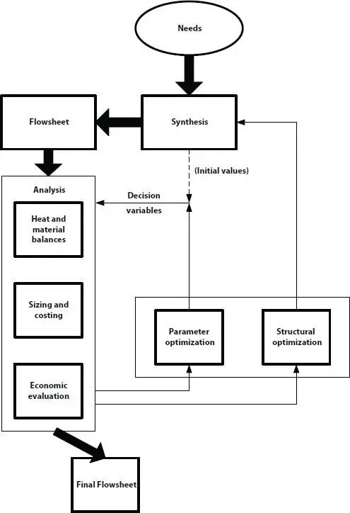
Figure 14.4 Partitioning the process design task into interrelated subtasks (source: Westerberg, et al . [8]).
14.5 Flowsheets—Types
The flowsheet is the “road-map” of a process, and serves to identify and focus the scope of the process for all interested and associated functions of the project. As a project progresses, the various engineering disciplines read their portions of responsibility from the flowsheet, although they may not understand the process or other details relative to some of the other phases of engineering. Here is where the process and/or project engineer serves to tie together these necessary segments of work. This often involves explanations sufficiently clear to enable these other groups to obtain a good picture of the objective and the problems associated with attaining it.
The flowsheet also describes the process to management as well as those concerned with preparing economic studies for process evaluation.
A good process flowsheet pictorially and graphically identifies the chemical process steps in proper sequence. It is done in such a manner and with sufficient detail to present to others a proper mechanical interpretation of the chemical requirements.
There are several types of flowsheets:
14.5.1 Block Diagram
This is usually used to set forth a preliminary or basic processing concept without details ( Figure 14.5). The blocks do not describe how a given step will be achieved, but rather what is to be done. These are often used in survey studies to management, research summaries, process proposals for “packaged” steps, and to “talk-out” a processing idea.
14.5.2 Process Flowsheet or Flow Diagram
This is used to present the heat balance and material balances of a process ( Figures 14.6a– 14.6c). This may be in broad block form with specific key points delineated, or in more detailed form identifying essentially every flow, temperature and pressure for each basic piece of process equipment or processing step. This may and usually does include auxiliary services to the process, such as steam, water, air, fuel gas, refrigeration, circulating oil, and so on. This type of sheet is not necessarily distributed to the same groups as would receive and need the piping flowsheet described next, because it may contain detailed confidential process data.
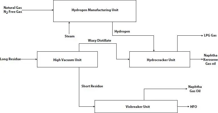
Figure 14.5 Block flow diagram of hydrocracker overview.
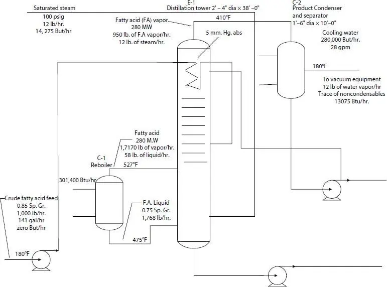
Figure 14.6a Heat and material balance-established material and thermal requirements [9].
14.5.3 Piping Flowsheet or Mechanical Flow Diagram, or Piping and Instrumentation Diagram (P&ID)
This is used to present “mechanical-type” details to piping and mechanical vessel designers, electrical engineers, instrument engineers, and other engineers not directly in need of process details ( Figures 14.7and 14.8). Piping and Instrument Diagrams (P&IDs) are graphical summary of the actual hardware elements in a petroleum refining and chemical process plant and their inter relationships of connections to form an operable, safe and reliable plant. The P&IDs include vessels (columns and tanks), pipe sizes, schedule (thickness), materials of construction, all valves (sizes and types), pumps, heat exchangers, reactors, furnaces, compressors, expanders, relief and drain valves, traps, filters, conveyors, hoppers, purchased subsystems, sensors, insulation requirements (thickness and type), controllers (flow, pressure, temperature, level), spares and other manufactured items, all in a logical configuration. The P&IDs do not include piping lengths and bends. In some engineering systems, detailed specifications cannot be completed until this flowsheet is basically complete.
Читать дальшеИнтервал:
Закладка:
Похожие книги на «Petroleum Refining Design and Applications Handbook»
Представляем Вашему вниманию похожие книги на «Petroleum Refining Design and Applications Handbook» списком для выбора. Мы отобрали схожую по названию и смыслу литературу в надежде предоставить читателям больше вариантов отыскать новые, интересные, ещё непрочитанные произведения.


Обсуждение, отзывы о книге «Petroleum Refining Design and Applications Handbook» и просто собственные мнения читателей. Оставьте ваши комментарии, напишите, что Вы думаете о произведении, его смысле или главных героях. Укажите что конкретно понравилось, а что нет, и почему Вы так считаете.