A. Kayode Coker - Petroleum Refining Design and Applications Handbook
Здесь есть возможность читать онлайн «A. Kayode Coker - Petroleum Refining Design and Applications Handbook» — ознакомительный отрывок электронной книги совершенно бесплатно, а после прочтения отрывка купить полную версию. В некоторых случаях можно слушать аудио, скачать через торрент в формате fb2 и присутствует краткое содержание. Жанр: unrecognised, на английском языке. Описание произведения, (предисловие) а так же отзывы посетителей доступны на портале библиотеки ЛибКат.
- Название:Petroleum Refining Design and Applications Handbook
- Автор:
- Жанр:
- Год:неизвестен
- ISBN:нет данных
- Рейтинг книги:3 / 5. Голосов: 1
-
Избранное:Добавить в избранное
- Отзывы:
-
Ваша оценка:
Petroleum Refining Design and Applications Handbook: краткое содержание, описание и аннотация
Предлагаем к чтению аннотацию, описание, краткое содержание или предисловие (зависит от того, что написал сам автор книги «Petroleum Refining Design and Applications Handbook»). Если вы не нашли необходимую информацию о книге — напишите в комментариях, мы постараемся отыскать её.
Petroleum Refining Design and Applications Handbook — читать онлайн ознакомительный отрывок
Ниже представлен текст книги, разбитый по страницам. Система сохранения места последней прочитанной страницы, позволяет с удобством читать онлайн бесплатно книгу «Petroleum Refining Design and Applications Handbook», без необходимости каждый раз заново искать на чём Вы остановились. Поставьте закладку, и сможете в любой момент перейти на страницу, на которой закончили чтение.
Интервал:
Закладка:
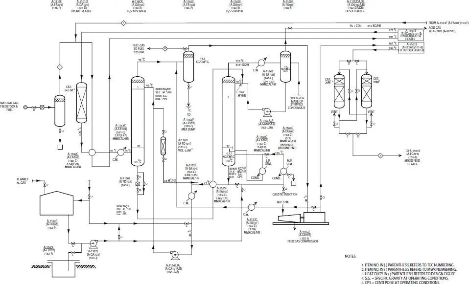
Figure 14.6bProcess flow diagram of (feed and fuel desulfurization sections) [9].
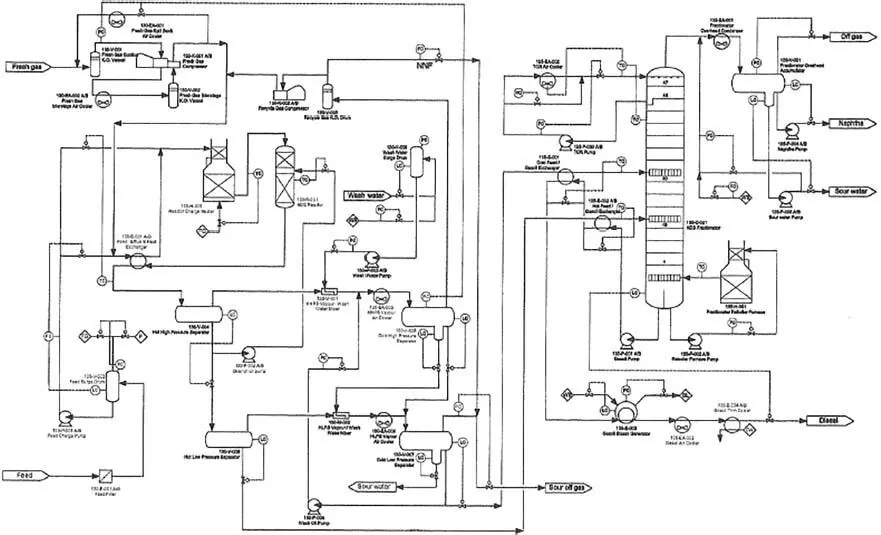
Figure 14.6c Process flow diagram of atmospheric fractionator.
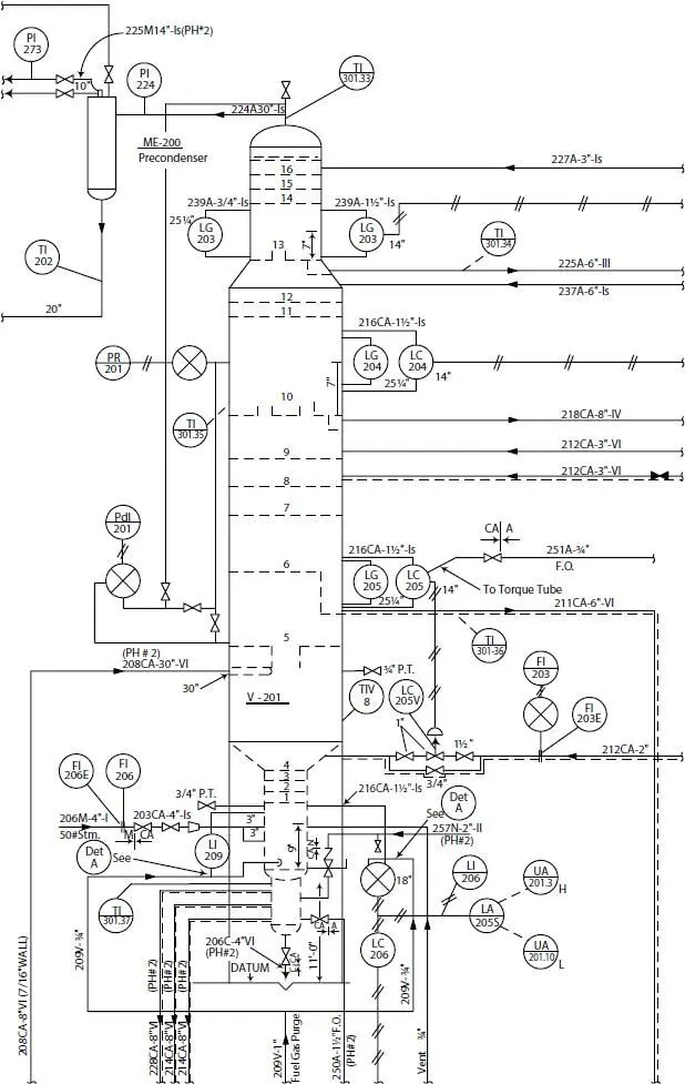
Figure 14.7 Mechanical detail flow diagram [9].
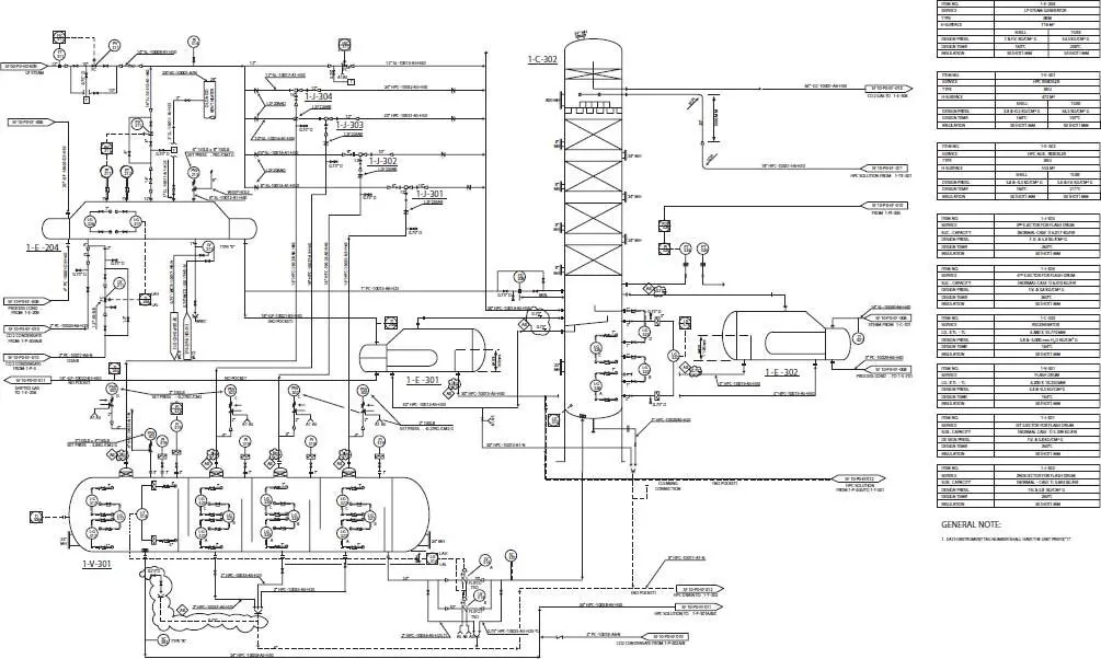
Figure 14.8 Piping and Instrumentation (P & ID) diagram for ammonia plant [9].
14.5.4 Combined Process and Piping Flowsheet or Diagram
This is used to serve the same purpose of both the process and piping flowsheets ( Figures 14.9and 14.10). This necessarily results in a drawing with considerably more detail than either of types 2 and 3 just discussed. However, the advantage is in concentrating the complete data and information for a project at one point. It does require close attention in proper reading and often opens data to larger groups of persons who might misinterpret or misuse it.
Some companies do not allow the use of this sheet in their work primarily because of the confidential nature of some of the process data. Where it is used, it presents a concise summary of the complete process and key mechanical data for assembly. This type of sheet requires more time for complete preparation, but like all engineering developments preliminary issues are made as information is available. Often the sheet is not complete until the piping and other detailed drawings are finished. This then is an excellent record of the process as well as a worksheet for training operators of the plant.
14.5.5 Utility Flowsheets or Diagrams (ULDs)
Utility line diagram (ULD) includes hardware details of the steam, water piping and control systems ( Figures 14.11and 14.12). Used to summarize and detail the interrelationship of utilities such as air, water (various types), steam (various types), heat transfer mediums such as Dowtherm, process vents and purges, safety relief blow-down, etc., to the basic process. The amount of detail is often too great to combine on other sheets, so separate sheets are prepared. These are quite valuable and time saving during the engineering of the project. They also identify the exact flow direction and sequence of tie-in relationships for the operating and maintenance personnel. The distribution of a utility such as steam is by a common distribution pipe, with each unit requiring the utility drawing its supply from that pipe. When a unit has taken its requirement, the utility distribution pipe can then be reduced in size as it continues to the next unit requiring the utility. The order of servicing units is affected by layout, and utility line sizes are affected by the order.
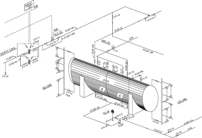
Figure 14.9 Piping details isometric diagram [9].
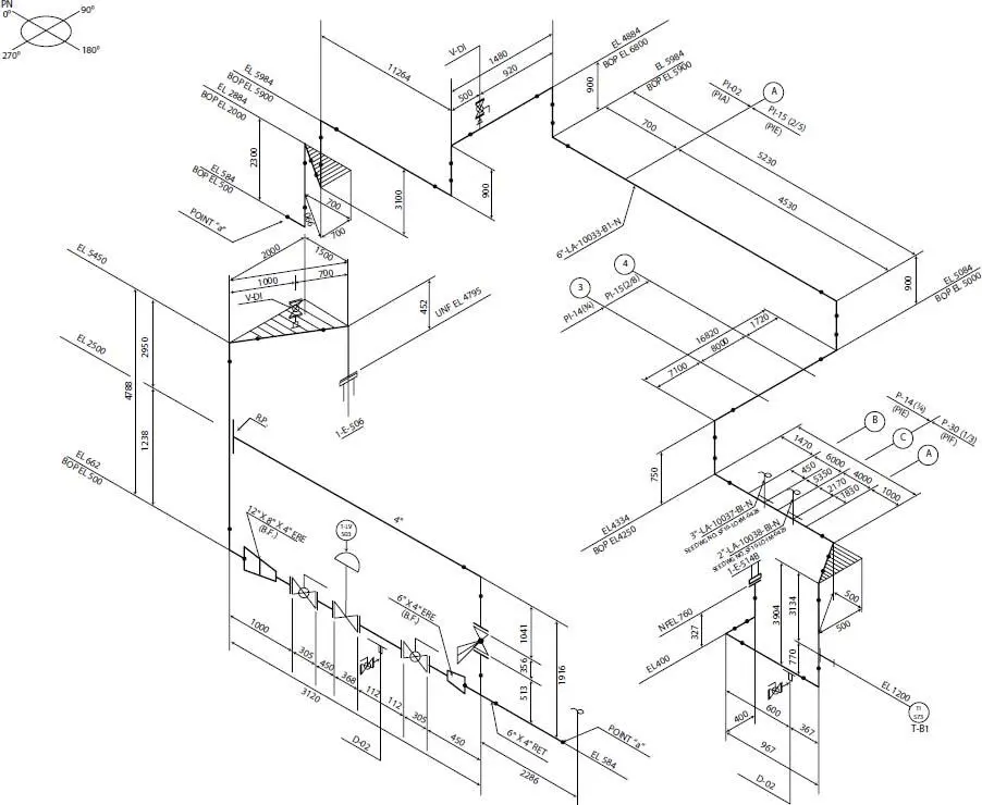
Figure 14.10 Isometric diagram of a process line [9].
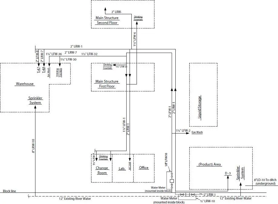
Figure 14.11 Standard type laying for service piping diagram.
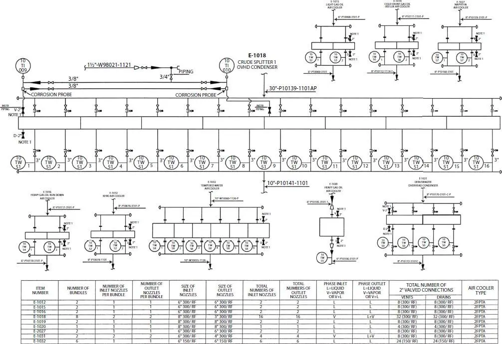
Figure 14.12 Process Engineering flow scheme (Crude distiller unit 1000 air cooler manifold) [9].
14.5.6 Special Flowsheets or Diagrams
From the basic process containing flowsheet, other engineering specialties develop their own details. For example, the instrument engineer often takes the requirements of the process and prepares a completely detailed flowsheet which defines every action of the instruments, control valves, switches, alarm horns, signal lights, etc. This is his/her detailed working tool.
The electrical engineer likewise takes basic process and plant layout requirements and translates them into details for the entire electrical performance of the plant. This will include the electrical requirements of the instrumentation in many cases, but if not, they must be coordinated. O’Donnell [10] has described the engineering aspects of these special flowsheets.
14.5.7 Special or Supplemental Aids
Plot Plans
Plot plans are necessary for the proper development of a final and finished process, piping or utility flowsheet ( Figure 14.13). After broad or overall layout decisions are made, the detailed layout of each processing area is not only helpful but necessary in determining the first realistic estimate of the routing, lengths and sequence of piping. This is important in such specifications as pipe sizing, and pump head and compressor discharge pressures. The nature of the fluids—whether hazardous, toxic, etc.—as well as the direction or location or availability for entrance to the area, definitely influences decisions regarding the equipment layout on the ground, in the structures, and in relation to buildings. Prevailing wind direction and any other unusual conditions should also be considered.
14.6 Flowsheet Presentation
Experienced flowsheet layout personnel all emphasize the importance of breaking processes into systems and logical parts of systems such as reaction, compression, separating, finishing, refrigeration, storage, etc., for detailed drafting. This point cannot be overemphasized, since considerably more space is needed for final completion of all details than is usually visualized at first. The initial layout of the key equipment should be spread farther than looks good to the eye. In fact, it probably looks wasteful of drawing space.
Later as process and sometimes service lines, valves, controls and miscellaneous small accessories are added this “extra” space will be needed to maintain an easily readable sheet. As this develops, attention should be given to the relative weights and styles of lines to aid in the readability of the sheets.
14.7 General Arrangements Guide
Each phase of the process is best represented on individual flowsheets. Electric power, fuel gas, drainage and the many other auxiliary system requirements are also best defined by separate individual flowsheets. These should be complete including all headers, branch take-offs, tie-ins to existing or known points, and so on. Only in this way can all the decisions as well as specifications be delineated for the various parts contributing to the entire project. The master process or mechanical flowsheet must contain specific references to the other sheets for continuation of the details and complete coordination.
Читать дальшеИнтервал:
Закладка:
Похожие книги на «Petroleum Refining Design and Applications Handbook»
Представляем Вашему вниманию похожие книги на «Petroleum Refining Design and Applications Handbook» списком для выбора. Мы отобрали схожую по названию и смыслу литературу в надежде предоставить читателям больше вариантов отыскать новые, интересные, ещё непрочитанные произведения.


Обсуждение, отзывы о книге «Petroleum Refining Design and Applications Handbook» и просто собственные мнения читателей. Оставьте ваши комментарии, напишите, что Вы думаете о произведении, его смысле или главных героях. Укажите что конкретно понравилось, а что нет, и почему Вы так считаете.