A. Kayode Coker - Petroleum Refining Design and Applications Handbook
Здесь есть возможность читать онлайн «A. Kayode Coker - Petroleum Refining Design and Applications Handbook» — ознакомительный отрывок электронной книги совершенно бесплатно, а после прочтения отрывка купить полную версию. В некоторых случаях можно слушать аудио, скачать через торрент в формате fb2 и присутствует краткое содержание. Жанр: unrecognised, на английском языке. Описание произведения, (предисловие) а так же отзывы посетителей доступны на портале библиотеки ЛибКат.
- Название:Petroleum Refining Design and Applications Handbook
- Автор:
- Жанр:
- Год:неизвестен
- ISBN:нет данных
- Рейтинг книги:3 / 5. Голосов: 1
-
Избранное:Добавить в избранное
- Отзывы:
-
Ваша оценка:
Petroleum Refining Design and Applications Handbook: краткое содержание, описание и аннотация
Предлагаем к чтению аннотацию, описание, краткое содержание или предисловие (зависит от того, что написал сам автор книги «Petroleum Refining Design and Applications Handbook»). Если вы не нашли необходимую информацию о книге — напишите в комментариях, мы постараемся отыскать её.
Petroleum Refining Design and Applications Handbook — читать онлайн ознакомительный отрывок
Ниже представлен текст книги, разбитый по страницам. Система сохранения места последней прочитанной страницы, позволяет с удобством читать онлайн бесплатно книгу «Petroleum Refining Design and Applications Handbook», без необходимости каждый раз заново искать на чём Вы остановились. Поставьте закладку, и сможете в любой момент перейти на страницу, на которой закончили чтение.
Интервал:
Закладка:
14.9 Flowsheet Symbols
To reduce detailed written descriptions on flowsheets, it is usual practice to develop or adopt a set of symbols and codes, which suit the purpose. Flowsheet symbol standardization has been developed by various professional and technical organizations for their particular fields. The American National Standard Institute (ANSI) has also adopted most of these symbols. The following symbols references are related and useful for many chemical and mechanical processes:
1 1. American National Standard Institute (ANSI) ( www.ansi.org)
2 2. American Institute of Chemical Engineers (AIChE) ( www.aiche.org)(a) Letter Symbols for Chemical Engineering, ANSI Y10.12
3 3. American Society of Mechanical Engineers (ASME) ( www.asme.org)(a) Graphic Symbols for Plumbing, ANSI and ASA Y32.4(b) Graphic Symbols for Railroads Maps and Profiles, ANSI or ASA Y32.7(c) Graphic Symbols for Fluid Power Diagrams, ANSI or ASA Y32.10(d) Graphic Symbols for Process Flow, ANSI or ASA Y32.11(e) Graphic Symbols for Mechanical and Acoustical Elements as Used in Schematic Diagrams, ANSI or ASA Y32.18(f) Graphic Symbols for Pipe Fittings, Valves and Piping, ANSI or ASA Z32.2.3(g) Graphic Symbols for Heating, Ventilating and Air Conditioning, ANSI or ASA Z32.2.4(h) Graphic Symbols for Heat–Power Apparatus, ANSI or ASA Z32.2.6
4 4. Instrument Society of America (ISA) ( www.isa.org)(a) Instrumentation Symbols and Identification, ISA-S5.1.
5 5. American Petroleum Institute (API) ( www.api.org)
6 6. British Standards Institute ( www.bsi-global.com)
Other symbols are established for specialized purposes. The physical equipment symbols established in some of these standards are often not as descriptive as those in the chemical, petrochemical, and petroleum industry is accustomed to using. The bare symbolic outlines given in some of the standards do not adequately illustrate the detail needed to make them useful. Accordingly, many process engineers develop additional detail to include on flowsheets, such as Figures 14.16a– eand 14.17a– c, which enhance the detail in many of these standards. Various types of processing suggest unique, yet understandable symbols, which do not fit the generalized forms.
Many symbols are pictorial which is helpful in representing process as well as control and mechanical operations. In general, experience indicates that the better the representation including relative location of connections, key controls and even utility connections, and service systems, the more useful will be the flowsheets for detailed project engineering and plant design.
To aid in readability by plant management as well as engineering and operating personnel, it is important that a set of symbols be developed as somewhat standard for a particular plant or company. Of course, these can be improved and modified with time and as needed, but with the basic forms and letters established, the sheets can be quite valuable. Many companies consider their flowsheets quite confidential since they contain the majority of key processing information, even if in summary form.
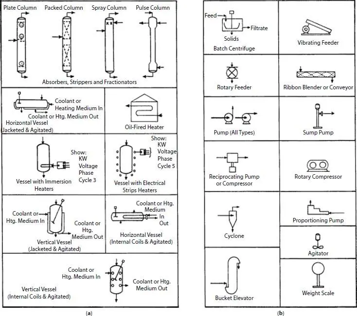
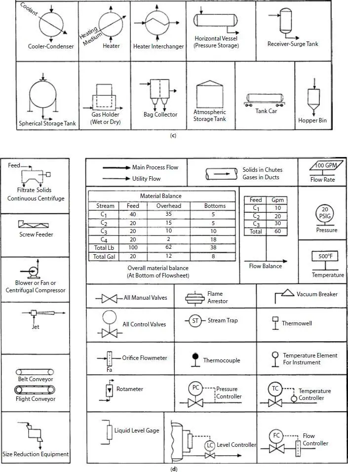
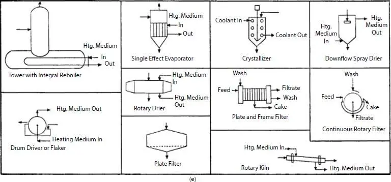
Figure 14.16 (a) Process variables; (b) Pumps and solids [9]. (c) Storage and equipment; (d) Flow and instruments [9]. (e) Filters, evaporators, and driers [9].
14.10 Line Symbols and Designations
The two types of lines on a flowsheet are (1) those representing outlines and details of equipment, instruments, and so on, and (2) those representing pipe carrying process or utility liquids, solids, or vapors and electrical or instrument connections. The latter must be distinguished among themselves as suggested by Figure 14.17d.
In order to represent the basic type of solution flowing in a line, designations or codes to assign to the lines can be developed for each process. Some typical codes are:
| RW | - River Water |
| TW | - Treated Water |
| SW | - Sea Water |
| BW | - Brackish Water |
| CW | - Chilled Water |
| S | - Low Pressure Steam |
| S150 | - 150 psi Steam |
| S400 | - 400 psi Steam |
| V | - Vent or Vacuum |
| C | - Condensate (pressure may be indicated) |
| D | - Drain to sewer or pit |
| EX | - Exhaust |
| M | - Methane |
| A- | - Air (or PA for Plant Air) |
| F | - Freon |
| G | - Glycol |
| SA | - Sulfuric Acid |
| B | - Brine |
| Cl | - Chlorine |
| P | - Process mixture (use for in-process lines not definitely designated by other symbols) |
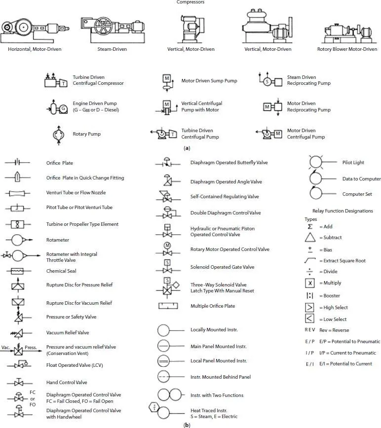
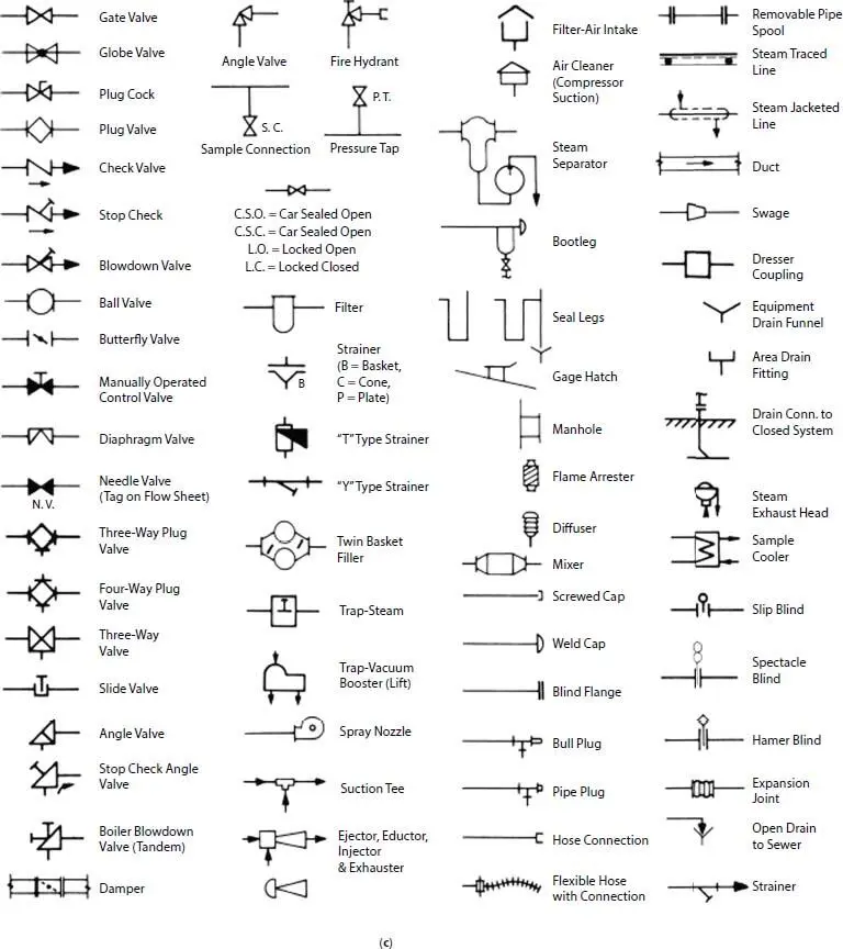
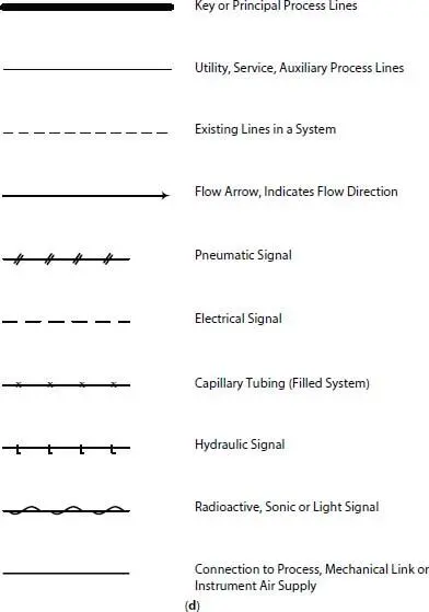
Figure 14.17 (a) Special types of descriptive flowsheet symbols [9]. (b) Commonly used instruments flowsheets [9]. (c) Flow diagram symbols. Valves, fittings, and miscellaneous piping [9]. (d) Line symbols (By permission from ISA Std. S51—1973 and 1984).
Sometimes it is convenient to prefix these symbols by L to indicate that the designation is for a line and not a vessel or instrument.
14.11 Materials of Construction for Lines
The process designer must also consider the corrosive nature of the fluids involved when selecting construction of materials for the various process and utility service lines. Some designers attach these materials designations to the line designation on the flowsheets, while others identify them on the Line Summary Table ( Figure 14.20d). Some typical pipe materials designations are:
| CS40 | - Carbon steel, Sch. 40 |
| CS80 | - Carbon steel, Sch. 80 |
| SS316/10 | - Stainless steel 316m Sch. 10 |
| GL/BE | - Glass bevel ends |
| N40 | - Nickel, Sch. 40 |
| TL/CS | - Teflon-lined carbon steel |
| PVC/CS Polyvinyl chloride | - lined CS |
| PP | - Solid polypropylene (designated weight sch) |
14.12 Test Pressure for Lines
The process designer also needs to designate the hydraulic test pressures for each line. This testing is performed after construction is essentially complete and often is conducted by testing sections of pipe systems, blanking off parts of the pipe or equipment, if necessary. Extreme care must be taken to avoid over pressuring any portion of pipe not suitable for a specific pressure, as well as extending test pressure through equipment not designed for that level. Vacuum systems must always be designed for “full vacuum,” regardless of the actual internal process absolute vacuum expected. This absolute zero designed basis will prevent the collapse of pipe and equipment should internal conditions vary. Some line design systems include the test pressure in the line code, but this often becomes too unwieldy for drafting purposes.
Читать дальшеИнтервал:
Закладка:
Похожие книги на «Petroleum Refining Design and Applications Handbook»
Представляем Вашему вниманию похожие книги на «Petroleum Refining Design and Applications Handbook» списком для выбора. Мы отобрали схожую по названию и смыслу литературу в надежде предоставить читателям больше вариантов отыскать новые, интересные, ещё непрочитанные произведения.


Обсуждение, отзывы о книге «Petroleum Refining Design and Applications Handbook» и просто собственные мнения читателей. Оставьте ваши комментарии, напишите, что Вы думаете о произведении, его смысле или главных героях. Укажите что конкретно понравилось, а что нет, и почему Вы так считаете.