A. Kayode Coker - Petroleum Refining Design and Applications Handbook
Здесь есть возможность читать онлайн «A. Kayode Coker - Petroleum Refining Design and Applications Handbook» — ознакомительный отрывок электронной книги совершенно бесплатно, а после прочтения отрывка купить полную версию. В некоторых случаях можно слушать аудио, скачать через торрент в формате fb2 и присутствует краткое содержание. Жанр: unrecognised, на английском языке. Описание произведения, (предисловие) а так же отзывы посетителей доступны на портале библиотеки ЛибКат.
- Название:Petroleum Refining Design and Applications Handbook
- Автор:
- Жанр:
- Год:неизвестен
- ISBN:нет данных
- Рейтинг книги:3 / 5. Голосов: 1
-
Избранное:Добавить в избранное
- Отзывы:
-
Ваша оценка:
Petroleum Refining Design and Applications Handbook: краткое содержание, описание и аннотация
Предлагаем к чтению аннотацию, описание, краткое содержание или предисловие (зависит от того, что написал сам автор книги «Petroleum Refining Design and Applications Handbook»). Если вы не нашли необходимую информацию о книге — напишите в комментариях, мы постараемся отыскать её.
Petroleum Refining Design and Applications Handbook — читать онлайн ознакомительный отрывок
Ниже представлен текст книги, разбитый по страницам. Система сохранения места последней прочитанной страницы, позволяет с удобством читать онлайн бесплатно книгу «Petroleum Refining Design and Applications Handbook», без необходимости каждый раз заново искать на чём Вы остановились. Поставьте закладку, и сможете в любой момент перейти на страницу, на которой закончили чтение.
Интервал:
Закладка:
The usual complete line designation contains the following: (1) line size (nominal); (2) material code; (3) sequence number; and (4) materials of construction (see and Figures 14.18and 14.20a– d).
| Examples: | 2″-CL6-CS40 |
| 3″-CL6a-CS40 | |
| 4″-RW1-CS40 | |
| 16″-S150-CS40 | |
| 3″-P-TL/CS |
Some engineers rearrange the sequence of the code although the information remains essentially the same. The line number sequence is conveniently arranged to start with one (1) or 100 for each of the fluid designations (CL, P, etc.). Since the sequence numbers are for coordination purposes and will appear on piping drawings, Line Schedule ( Figure 14.20athrough d), the number has no significance in itself. It is convenient to start numbering with the first process flow sheet and carry on sequentially to each succeeding sheet. Sometimes, however, this is not possible when several detailers are preparing different sheets, so each sheet can be given arbitrary beginning numbers such as 100, 300, 1000, etc. Although the sequential number may be changed as the line connects from equipment to equipment, it is often convenient to use the system concept and apply alphabetical suffixes to the sequence number as shown in Figures 14.18and 14.19. This contributes materially to the readability of the flowsheets. Each line on the flowsheet must represent an actual section or run of piping in the final plant and on the piping drawings.
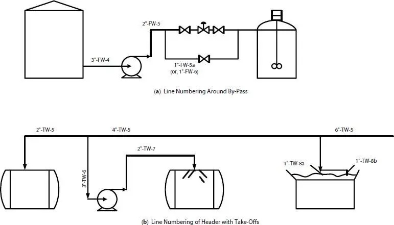
Figure 14.18 Examples of line numbering.
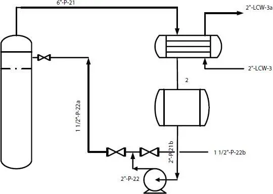
Figure 14.19 Use of alphabetic suffixes with line symbols.
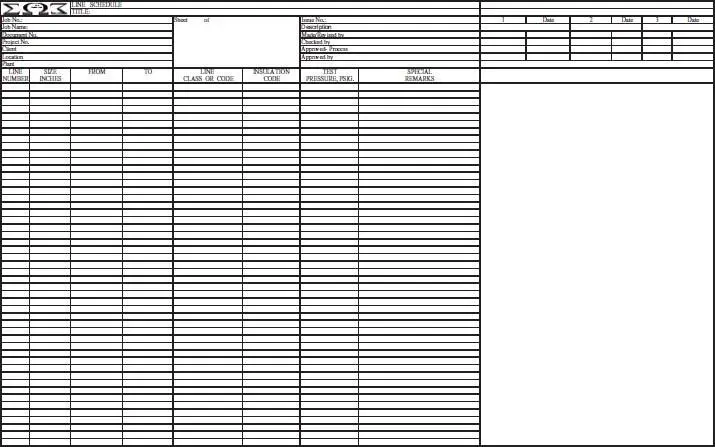
Figure 14.20a Line schedule.
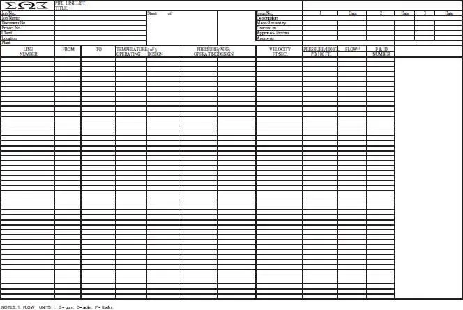
Figure 14.20bPipe line list.
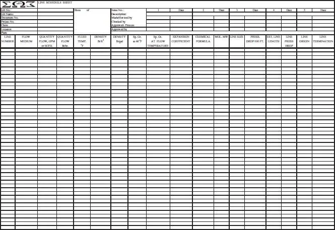
Figure 14.20cLine schedule sheet.
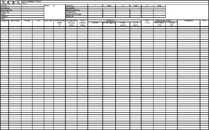
Figure 14.20d Line summary table.
Suggested guides for line identification for any one principal fluid composition:
1 1. Main headers should keep one sequence number ( Figure 14.18).
2 2. New sequence numbers should be assigned:(a) Upon entering and leaving an item of equipment.(b) To take-off or branch lines from main headers.(c) To structural material composition of line changes.
3 3. Alphabetical suffixes should be used in the following situations as long as clarity of requirements is clear, otherwise add new sequence numbers.(a) For secondary branches from headers or header branches.(b) For by-pass lines around equipment, control valves, etc. Keep same sequence number as the inlet or upstream line ( Figure 14.18).(c) For identical multiple systems, piping corresponding identical service items, and lines.
In order to coordinate the process flowsheet requirements with the mechanical piping specifications, Line Schedules are prepared as shown in Figures 14.20athrough d. The complete pipe system specifications are summarized by codes on these schedules.
Equipment code designations can be developed to suit the particular process, or as is customary a master coding can be established and followed for all projects. A suggested designation list (not all inclusive for all processes) for the usual process plant equipment is given in Table 14.4and process functions in Table 14.5. The various items are usually numbered by type and in process flow order as set forth on the flowsheets. For example:
Table 14.4 A system of equipment designations.
| AD | - Air Drier |
| AF | - Air Filter |
| Ag | - Agitator |
| B | - Blower |
| BR | - Barometric Refrigeration Unit |
| C | - Compressor |
| CP | - Car Puller |
| CT | - Cooling Tower |
| CV | - Conveyor |
| D | - Drum or tank |
| DS | - Desuperheater |
| E | - Heat Exchanger, condenser, reboiler, etc. |
| Ej | - Jet Ejector |
| Ex | - Expansion Joint |
| F | - Fan |
| FA | - Flame Arrestor |
| Fi | - Filter (line type, tank, centrifugal) |
| GT | - Gas Turbine |
| MB | - Motor for Blower |
| MC | - Motor for Compressor |
| MF | - Motor for Fan |
| MP | - Motor for Pump |
| P | - Pump |
| PH | - Process Heater or Furnace |
| R | - Reactor |
| S | - Separator |
| St | - Strainer |
| ST | - Steam Turbine |
| Str | - Steam trap |
| SV | - Safety Valve |
| Tr | - Trap |
| V | - Valve |
| VRV | - Vacuum Relief Valve |
| Item Code | Represents |
| C-1a | Three compressors of identical size operating in the same process service, connected in parallel. |
| C-1b | |
| C-1c | |
| C-2 | Single compressor in different service (by fluid or compression ratio) from C-1’s above. S-1 First separator in a process |
| S-2 | Second separator in a process |
| S-3a | Two identical separators connected in parallel, in the same process service. |
| S-3b |
Some equipment code systems number all items on first process flowsheet with 100 series, as C-101, C-102, P-106 to represent compressors number 101 and 102 in different services and pump 106 as the sixth pump on the sheet. The second sheet uses the 200 series, etc. This has some engineering convenience but is not always clear from the process view.
To keep process continuity clear, it is usually best to number all like items sequentially throughout the process, with no concern for which flowsheet they appear on. Also, another popular numbering arrangement is to identify a system such as reaction, drying, separation, purification, incineration, vent, and cooling tower waters and number all like process items within that system for example:
Table 14.5 Typical identification for flowsheet process functions.
| AS | - Air Supply |
| BD | - Blowdown |
| BF | - Blind Flange |
| CBD | - Continuous Blowdown |
| CD | - Closed Drain |
| CH-O | - Chained Operated |
| CSO | - Car Seal Open |
| CSC | - Car Seal Closed |
| DC | - Drain Connection |
| EBD | - Emerg. Blowdown Valve |
| ESD | - Emerg. Shutdown |
| FC | - Fail Closed |
| FO | - Fail Open |
| HC | - Hose Connection |
| IBD | - Intermittent Blowdown |
| LO | - Lock Open |
| ML | - Manual Loading |
| NC | - Normally Closed |
| NO | - Normally Open |
| OD | - Open Drain |
| P | - Personnel Protection |
| QO | - Quick Opening |
| SC | - Sample Protection |
| SO | - Steam Out |
| TSO | - Tight Shut Off |
| VB | - Vacuum Breaker |
| Reactor System, R: | Reactor is RD-1 |
| Reactor vent cooler is RE-1 | |
| Reactor vent condenser is RE-2 | |
| Reactor recycle pump is RP-1 | |
| Level control valve is RLC-1 | |
| Relief valve is RSV-1 |
Then, establish the same concept for all other unit or block processing systems. This is often helpful for large projects, such as refinery or grass roots chemical processes. Valve identification codes are usually used in preference to placing each valve specification on the flowsheet. This latter method is feasible for small systems, and is most workable when a given manufacturer (not necessarily the same manufacturer for all valves) can be selected and his valve catalog figure number used on the flowsheet. For large jobs, or where many projects are in progress at one time, it is common practice to establish valve specifications for the various process and utility services (see Figures 14.21and 14.22) by manufacturers’ catalog figure numbers. These are coded as V-11, V-12, V-13, etc., and such code numbers are used on the flowsheets whenever these valves are required (also see Figures 14.8and 14.9). By completely defining the valve specification in a separate specification book the various valves—gate, globe, butterfly, plug, flanged end, screwed end, welding end—can be identified for all persons involved on a project, including piping engineers and field erection contractors.
Читать дальшеИнтервал:
Закладка:
Похожие книги на «Petroleum Refining Design and Applications Handbook»
Представляем Вашему вниманию похожие книги на «Petroleum Refining Design and Applications Handbook» списком для выбора. Мы отобрали схожую по названию и смыслу литературу в надежде предоставить читателям больше вариантов отыскать новые, интересные, ещё непрочитанные произведения.


Обсуждение, отзывы о книге «Petroleum Refining Design and Applications Handbook» и просто собственные мнения читателей. Оставьте ваши комментарии, напишите, что Вы думаете о произведении, его смысле или главных героях. Укажите что конкретно понравилось, а что нет, и почему Вы так считаете.