A. Kayode Coker - Petroleum Refining Design and Applications Handbook
Здесь есть возможность читать онлайн «A. Kayode Coker - Petroleum Refining Design and Applications Handbook» — ознакомительный отрывок электронной книги совершенно бесплатно, а после прочтения отрывка купить полную версию. В некоторых случаях можно слушать аудио, скачать через торрент в формате fb2 и присутствует краткое содержание. Жанр: unrecognised, на английском языке. Описание произведения, (предисловие) а так же отзывы посетителей доступны на портале библиотеки ЛибКат.
- Название:Petroleum Refining Design and Applications Handbook
- Автор:
- Жанр:
- Год:неизвестен
- ISBN:нет данных
- Рейтинг книги:3 / 5. Голосов: 1
-
Избранное:Добавить в избранное
- Отзывы:
-
Ваша оценка:
Petroleum Refining Design and Applications Handbook: краткое содержание, описание и аннотация
Предлагаем к чтению аннотацию, описание, краткое содержание или предисловие (зависит от того, что написал сам автор книги «Petroleum Refining Design and Applications Handbook»). Если вы не нашли необходимую информацию о книге — напишите в комментариях, мы постараемся отыскать её.
Petroleum Refining Design and Applications Handbook — читать онлайн ознакомительный отрывок
Ниже представлен текст книги, разбитый по страницам. Система сохранения места последней прочитанной страницы, позволяет с удобством читать онлайн бесплатно книгу «Petroleum Refining Design and Applications Handbook», без необходимости каждый раз заново искать на чём Вы остановились. Поставьте закладку, и сможете в любой момент перейти на страницу, на которой закончили чтение.
Интервал:
Закладка:
Figure 14.2diagrammatically suggests a team arrangement for accomplishing the planning of a process project. The arrows indicate directions of flow of communications and also the tie-in relationship of the process design function in the accomplishment of an assignment. The planning team in the box works to place the proper perspective on all phases of the engineering functions by developing a working atmosphere of understanding for accomplishing the engineering design. This is physically represented by mechanical vessels, piping, structures, electrical, instrumentation, civil and any other specialized functions. In many projects, the Lead Process Engineer and the Project Lead Engineer are the only individuals who see the details of the overall scope of the project.
14.2.1 Process Design Scope
The project engineer appoints a chief process engineer who puts together a process design team to be responsible for all the chemical engineering aspects of the plant. The term “process design” is used here to include what is sometimes referred to as process engineering. Yet in some process engineering operations, all process design functions may not be carried out in detail. As discussed, process design is intended to include the following:
1 1. Process material and heat balances.
2 2. Process cycle development, correlation of pilot or research data, and correlation of physical property data.
3 3. Auxiliary services material and heat balances.
4 4. Flowsheet development and detailed completion.
5 5. Chemical engineering performance design for specific items of equipment required for a flowsheet, and mechanical interpretation of this to a practical and reasonable specification. Here, the process requirements are converted into hardware details to accomplish the process end results at each step in the product production process.
6 6. Instrumentation as related to process performance, presentation, and interpretation of requirements to instrument specialists.
7 7. Process interpretation for proper mechanical, structural, civil, electrical, instrument, and so on, handling of the respective individual phases of the project.
8 8. Preparation of specifications in proper form and/or detail for use by the project team as well as for the purchasing function.
9 9. Evaluation of bids and recommendation of qualified vendor.
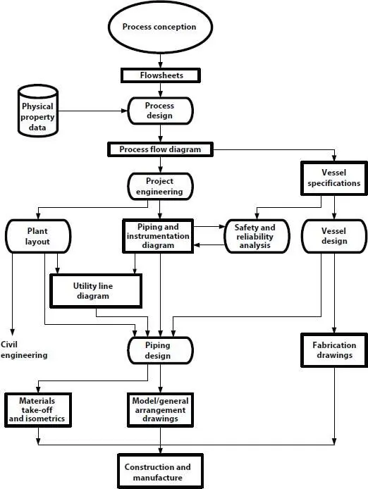
Figure 14.3 The total plant design project.
Most of the functions are fairly self-explanatory; therefore, emphasis will be placed only on those requiring detailed explanation. Another process design scope issue for the process design team is to identify and scope any key layout issues early in the design effort or basic engineering and Front End Engineering Design (FEED). Such issues include concerns like:
1 1. Locations where gravity feed is used.
2 2. Product quality concerns where product residence times must be minimized
3 3. Equipment requiring easy access for maintenance.
Figure 14.3provides an overview of the total plan design project.
14.3 Role of the Process Design Engineer
Although the working role of the process design engineer may include all of the technical requirements listed above, it is very important to recognize what this entails in some detail. The process design engineer, in addition to being capable of participating in evaluation of research and pilot plant data and the conversion of this data into a proposed commercial process scheme, must also perform the following functions:
1 1. Prepare heat and mass balance studies for a proposed process, both “by hand” and by use of computer programs. The use of a spreadsheet package (e.g., Excel) is now prevalent in accomplishing these calculations. Simulation software products from vendors are now apt in performing these tasks.
2 2. Prepare rough cost economics, including preliminary sizing and important details of equipment, factor to an order of magnitude capital cost estimate [3] (see also [2]), prepare a production cost estimate and work with economic evaluation representatives to establish a payout and the financial economics of the proposed process.
3 3. Participate in layout planning for the proposed plant (see [4, 5]).
4 4. Prepare final detailed heat and material balances.
5 5. Prepare detailed sizing of all process equipment and possibly some utility systems. It is important that the process engineer visualizes the flow and processing of the fluids through the system and inside the various items of equipment in order to adequately recognize what will take place during the process.
6 6. Prepare/supervise preparation of draft of process flowsheets for review by others.
7 7. Prepare/supervise preparation of piping or mechanical flow diagram or piping and instrumentation diagram (P&ID), with necessary preliminary sizing of all pipe lines, distillation equipment, pumps, compressors, and so on, and representation of all instrumentation for detailing by instrument engineers.
8 8. Prepare mechanical and process specifications for all equipment, tanks, pumps, compressors, separators, drying systems, and refrigeration systems. This must include the selection of materials of construction and safety systems and the coordination of specifications with instrumentation and electrical requirements.
9 9. Determine size and specifications for all safety relief valves and/or rupture disks for process safety relief (including runaway reactions) and relief in case of external fire.
10 10. Prepare valve code specifications for incorporation on item 7 above, or select from existing company standards for the fluids and their operating conditions (see Figures 14.21and 14.22).
11 11. Select from company insulation standards (or prepare, if necessary) the insulation codes to be applied to each hot or cold pipe or equipment. Note that insulation must be applied in some cases only to prevent operating personnel from contacting the base equipment. Table 14.1for typical insulation thickness from which code numbers can be established.
12 12. Establish field construction hydraulic test pressures for each process equipment. Sometimes the equipment is blanked or blocked off, and no test pressure is applied in the field, because all pressure equipment must be tested in the fabricators’ or manufacturers’ shop as per American Society of Mechanical Engineers (ASME) Code.
13 13. Prepare drafts of line schedule and/or summary sheets ( Figures 14.20a– 14.20d), and equipment summary schedules ( Figures 14.23– 14.28), plus summary schedules for safety relief valves and rupture disks, compressors and other major equipment. Some of the process data sheets and equipment schedules (over 30) are readily available for downloading from the companion website.
14 14. Prepare detailed process and mechanical specifications for developing proposals for purchase by the purchasing department.
15 15. Participate and possibly lead the process hazard reviews (i.e., hazard and operability studies, (HAZOP) (Chapter 24).
Table 14.1 Typical thickness chart—insulation for services 70°F through 1200°F piping, vessels, and equipment 36” diameter and smaller.
| Insulation thickness | |||||
| Pipe size | 1” | 1½” | 2” | 2½” | 3” |
| ≤2½” | 700°F | 1000°F | 1200°F | ||
| ≤3” | 700 | 900 | 1100 | 1200°F | |
| ≤4” | 700 | 900 | 1100 | 1200 | |
| ≤6” | 600 | 800 | 1000 | 1200 | |
| ≤8” | – | 800 | 1000 | 1200 | |
| ≤10” | – | 800 | 1000 | 1200 | |
| ≤12” | – | 800 | 1000 | 1200 | |
| ≤14” | – | 800 | 1000 | 1100 | 1200°F |
| ≤16” | – | 800 | 900 | 1100 | 1200 |
| ≤18” | – | 800 | 900 | 1100 | 1200 |
| ≤20” | – | 800 | 900 | 1100 | 1200 |
| ≤24” | – | 800 | 900 | 1100 | 1200 |
| ≤30” | – | 800 | 900 | 1100 | 1200 |
| ≤36” | – | 800 | 900 | 1000 | 1200 |
Notes: 1.Temperatures in chart are maximum operating temperatures in degrees Fahrenheit for given thickness.
Читать дальшеИнтервал:
Закладка:
Похожие книги на «Petroleum Refining Design and Applications Handbook»
Представляем Вашему вниманию похожие книги на «Petroleum Refining Design and Applications Handbook» списком для выбора. Мы отобрали схожую по названию и смыслу литературу в надежде предоставить читателям больше вариантов отыскать новые, интересные, ещё непрочитанные произведения.


Обсуждение, отзывы о книге «Petroleum Refining Design and Applications Handbook» и просто собственные мнения читателей. Оставьте ваши комментарии, напишите, что Вы думаете о произведении, его смысле или главных героях. Укажите что конкретно понравилось, а что нет, и почему Вы так считаете.