A. Kayode Coker - Petroleum Refining Design and Applications Handbook
Здесь есть возможность читать онлайн «A. Kayode Coker - Petroleum Refining Design and Applications Handbook» — ознакомительный отрывок электронной книги совершенно бесплатно, а после прочтения отрывка купить полную версию. В некоторых случаях можно слушать аудио, скачать через торрент в формате fb2 и присутствует краткое содержание. Жанр: unrecognised, на английском языке. Описание произведения, (предисловие) а так же отзывы посетителей доступны на портале библиотеки ЛибКат.
- Название:Petroleum Refining Design and Applications Handbook
- Автор:
- Жанр:
- Год:неизвестен
- ISBN:нет данных
- Рейтинг книги:3 / 5. Голосов: 1
-
Избранное:Добавить в избранное
- Отзывы:
-
Ваша оценка:
Petroleum Refining Design and Applications Handbook: краткое содержание, описание и аннотация
Предлагаем к чтению аннотацию, описание, краткое содержание или предисловие (зависит от того, что написал сам автор книги «Petroleum Refining Design and Applications Handbook»). Если вы не нашли необходимую информацию о книге — напишите в комментариях, мы постараемся отыскать её.
Petroleum Refining Design and Applications Handbook — читать онлайн ознакомительный отрывок
Ниже представлен текст книги, разбитый по страницам. Система сохранения места последней прочитанной страницы, позволяет с удобством читать онлайн бесплатно книгу «Petroleum Refining Design and Applications Handbook», без необходимости каждый раз заново искать на чём Вы остановились. Поставьте закладку, и сможете в любой момент перейти на страницу, на которой закончили чтение.
Интервал:
Закладка:
2 2. For 3.8–38 m3 (1000–10,000 gal.), use horizontal tanks on concrete supports.
3 3. Beyond 38 m3 (10,000 gal.) use vertical tanks on concrete foundations.
4 4. Liquids subject to breathing losses may be stored in tanks with floating or expansion roofs for conservation.
5 5. Freeboard is 15% below 1.9 m3 (500 gal.) and 10% above 1.9 m3 (500 gal.) capacity.
6 6. A 30-day capacity often is specified for raw materials and products but depends on connecting transportation equipment schedules.
7 7. Capacities of storage tanks are at least 1.5 times the size of connecting transportation equipment; for instance, 28.4-m3 (7500 gal.) tanker trucks, 130-m3 (34,500 gal.) rail cars, and virtually unlimited barge and tanker capacities.
Source : The above mentioned rules of thumb have been adapted from Walas, S.M., Chemical Process Equipment: Selection and Design , copyright 1988 with permission from Elsevier, all rights reserved.
Physical Properties Heuristics.
| Units | Liquids | Liquids | Gases | Gases | Gases | |
|---|---|---|---|---|---|---|
| Water | Organic material | Steam | Air | Organic material | ||
| Heat capacity | kJ/kg °C | 4.2 | 1.0–2.5 | 2.0 | 1.0 | 2.0–4.0 |
| Density | kg/m3 | 1000 | 700–1500 | 1.29 at STP | ||
| Latent heat | kJ/kg | 1200–2100 | 200–1000 | |||
| Thermal conductivity | W/m °C | 0.55–0.70 | 0.10–0.20 | 0.025–0.07 | 0.025–0.05 | 0.02–0.06 |
| Viscosity | kg/ms | 0°C 1.8 × 10 −3 | Wide Range | 10–30 × 10 −6 | 20–50 × 10 −6 | 10–30 × 10 −6 |
| 50°C 5.7 × 10 −4 | ||||||
| 100°C 2.8 × 10 −4 | ||||||
| 200°C 1.4 × 10 −4 | ||||||
| Prandtl no. | 1–15 | 10–1000 | 1.0 | 0.7 | 0.7–0.8 |
Source : Turton, R. et al ., Analysis, Synthesis, and Design of Chemical Process , Prentice Hall International Series, 2001.
Typical Physical Property Variations with Temperature and Pressure.
| Liquids | Liquids | Gases | Gases | |
|---|---|---|---|---|
| Property | Temperature | Pressure | Temperature | Pressure |
| Density | 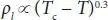 |
Negligible | ρ g= MW P / ZRT | ρ g= MW P / ZRT |
| Viscosity | μ 1= Ae B/T | Negligible | 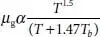 |
Significant only for >10 bar |
| Vapor pressure | P* = ae b/(T+c) | – | – | – |
Note : T is temperature (K), T cis the critical Temperature (K), T bis the normal boiling point (K), MV is molecular weight, P is pressure, Z is compressibility, R is the gas constant, and P * is the vapor pressure.
Source : Turton, R. et al ., Analysis, Synthesis, and Design of Chemical Processes , Prentice Hall International Series, 2001.
Capacities of Process Units in Common Usagea.
| Process unit | Capacity unit | Maximum value | Minimum value | Comment | |
|---|---|---|---|---|---|
| Horizontal vessel | Pressure (bar) | 400 | Vacuum | L/D typically 2–5 | |
| Temperature (°C) | 400 b | −200 | |||
| Height (m) | 10 | 2 | |||
| Diameter (m) | 2 | 0.3 | |||
| L/D | 5 | 2 | |||
| Vertical vessel | Pressure (bar) | 400 | 400 | L/D typically 2–5 | |
| Temperature (°C) | 400 b | −200 | |||
| Height (m) | 10 | 2 | |||
| Diameter (m) | 2 | 0.3 | |||
| L/D | 5 | 2 | |||
| Towers | Pressure (bar) | 400 | Vacuum | Normal Limits Diameter | L/D |
| Temperature (°C) | 400 b | −200 | 0.5 | 3.0–40 c | |
| Height (m) | 50 | 2 | 1.0 | 2.5–30 c | |
| Diameter (m) | 4 | 0.3 | 2.0 | 1.6–23 c | |
| L/D | 30 | 2 | 4.0 | 1.8–13 c | |
| Pumps | |||||
| Reciprocating | Power d (kW) | 250 | <0.1 | ||
| Pressure (bar) | 1000 | ||||
| Rotary and positive | Power d (kW) | 150 | <0.1 | ||
| Displacement | Pressure (bar) | 300 | |||
| Centrifugal | Power d (kW) | 250 | <0.1 | ||
| Pressure (bar) | 300 | ||||
| Compressors | |||||
| Axial, Centrifugal + Recipr. | Power d (kW) | 8000 | 50 | ||
| Rotary | Power d (kW) | 1000 | 50 | ||
| Drives for compressor | |||||
| Electric | Power e (kW) | 15,000 | <1 | ||
| Steam turbine | Power e (kW) | 15,000 | 100 | ||
| Gas turbine | Power e (kW) | 15,000 | 10 | ||
| Internal combustion eng. | Power e (kW) | 15,000 | 10 | ||
| Process heaters | Duty (MJ/h) | 500,000 | 10,000 | Duties different for reactive heaters/furnaces | |
| Heat exchangers | Area (m 2) | 1000 | 10 | For Area <10 m 2use | |
| Tube Dia. (m) | 0.0254 | 0.019 | double-pipe exchanger | ||
| Length (m) | 6.5 | 2.5 | |||
| Pressure (bar) | 150 | Vacuum | For 150 < P < 400 bar | ||
| Temperature (°C) | 400 b | −200 | need special design |
aMost of the limits for equipment sizes shown here correspond to the limits used in the costing program (CAPCOST.BAS).
b Maximum temperature and pressure are related to the materials of construction and may differ from values shown here.
c For 20 < L/D < 30 special design may be required. Diameter up to 7 m possible but over 4 m must be fabricated on site.
d Power values refer to fluid/pumping power.
e Power values refer to shaft power.
Source : Turton, R. et al ., Analysis, Synthesis, and Design of Chemical Processes , Prentice Hall International Series, 2001.
Читать дальшеИнтервал:
Закладка:
Похожие книги на «Petroleum Refining Design and Applications Handbook»
Представляем Вашему вниманию похожие книги на «Petroleum Refining Design and Applications Handbook» списком для выбора. Мы отобрали схожую по названию и смыслу литературу в надежде предоставить читателям больше вариантов отыскать новые, интересные, ещё непрочитанные произведения.


Обсуждение, отзывы о книге «Petroleum Refining Design and Applications Handbook» и просто собственные мнения читателей. Оставьте ваши комментарии, напишите, что Вы думаете о произведении, его смысле или главных героях. Укажите что конкретно понравилось, а что нет, и почему Вы так считаете.