Mohamed N. Rahaman - Materials for Biomedical Engineering
Здесь есть возможность читать онлайн «Mohamed N. Rahaman - Materials for Biomedical Engineering» — ознакомительный отрывок электронной книги совершенно бесплатно, а после прочтения отрывка купить полную версию. В некоторых случаях можно слушать аудио, скачать через торрент в формате fb2 и присутствует краткое содержание. Жанр: unrecognised, на английском языке. Описание произведения, (предисловие) а так же отзывы посетителей доступны на портале библиотеки ЛибКат.
- Название:Materials for Biomedical Engineering
- Автор:
- Жанр:
- Год:неизвестен
- ISBN:нет данных
- Рейтинг книги:4 / 5. Голосов: 1
-
Избранное:Добавить в избранное
- Отзывы:
-
Ваша оценка:
Materials for Biomedical Engineering: краткое содержание, описание и аннотация
Предлагаем к чтению аннотацию, описание, краткое содержание или предисловие (зависит от того, что написал сам автор книги «Materials for Biomedical Engineering»). Если вы не нашли необходимую информацию о книге — напишите в комментариях, мы постараемся отыскать её.
A comprehensive yet accessible introductory textbook designed for one-semester courses in biomaterials Materials for Biomedical Engineering: Fundamentals and Applications
Materials for Biomedical Engineering: Fundamentals and Applications
Materials for Biomedical Engineering — читать онлайн ознакомительный отрывок
Ниже представлен текст книги, разбитый по страницам. Система сохранения места последней прочитанной страницы, позволяет с удобством читать онлайн бесплатно книгу «Materials for Biomedical Engineering», без необходимости каждый раз заново искать на чём Вы остановились. Поставьте закладку, и сможете в любой момент перейти на страницу, на которой закончили чтение.
Интервал:
Закладка:
| Crystal structure | Simple cubic | BCC | FCC | CPH |
|---|---|---|---|---|
| Atomic packing fraction | 0.52 | 0.68 | 0.74 | 0.74 |
While the majority of metals and a significant number of ceramics have a BCC, FCC, or CPH structure, these are not the only types of crystal structure in materials. In general, the crystal structure that a material adopts is the one that gives the minimum energy. This structure does not have to be close‐packed or geometrically simple but it must have a regular‐repeating ordered three‐dimensional pattern.
3.2.1 Unit Cells and Crystal Systems
A standard nomenclature is used to succinctly describe the geometrical arrangement of the atoms in a unit cell and, thus, in a crystal.
Unit Cell Parameters
The unit cell of a crystal is defined in terms of the length of the cell edges from a given lattice point, taken as the origin, and the angle between the cell edges ( Figure 3.5). The general convention in orienting a crystal is to use a coordinate system in which the x‐ axis points toward us as we look directly at the page, the y‐ axis points to the right, the z‐ axis points upward, and the origin is the point of intersection of the three axes. Then, the unit cell dimensions are taken as the edge lengths a , b , and c , respectively, in the x , y , and z directions. The angle between the edges b and c , that is, opposite the edge a , is taken as α, the angle between the edges a and c , opposite the edge b , is β, and the angle between the edges a and b , opposite the edge c , is γ. The lattice constants are the edge lengths a , b , and c , and the angles α, β, and γ, which define the crystal structure. The cubic structure, for example, has a = b = c and α = β = γ = 90°.
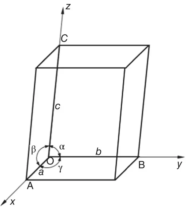
Figure 3.5 Geometry and parameters of a unit cell.
Crystal Systems and Bravais Lattices
There are seven different unit cell shapes, called crystal systems, defined by their unit cell lengths and interaxial angles ( Figure 3.6). When packed together, each of these seven unit cell shapes fills up three‐dimensional space completely. The unit cell contents are specified in terms of where the atoms are located. Consequently, depending on the location of the atoms in the unit cell, some crystal systems can generate more than one crystal lattice. The cubic system, for example, can generate three different crystal lattices, the simple cubic, BCC and FCC lattice. In total, there are 14 different crystal lattices, called Bravais lattices ( Figure 3.7).
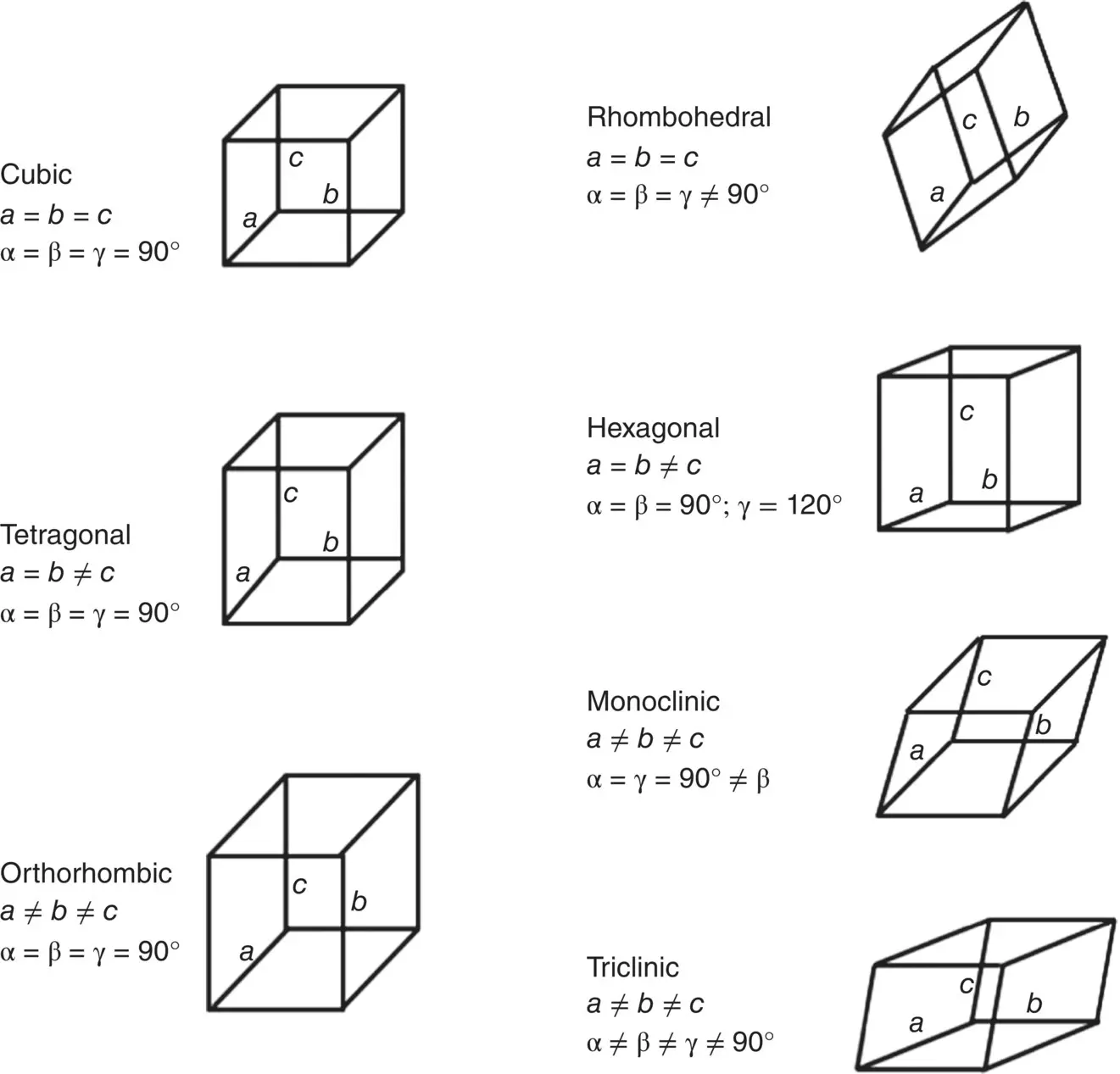
Figure 3.6 The seven crystal systems and their parameters.
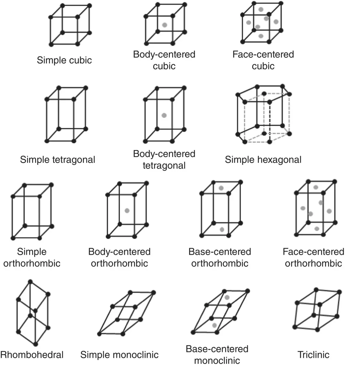
Figure 3.7 The 14 Bravais lattices.
Different planes and directions in crystalline solids can have a different arrangement of atoms as, for example, in a pure metal such as Ti. Depending on the composition of the solid, different planes and directions can also have a different combination of atoms. Some planes in sodium chloride (NaCl), for example, have different ratios of sodium to chlorine atoms. Consequently, some solids can show different properties in different planes or directions. Often, it is necessary to describe specific atomic positions, lattice planes or lattice directions in a succinct way. How this is done is described in Section 3.6.
3.3 Structure of Solids Used as Biomaterials
As pure metals are composed of a single type of atom, their crystal structures are rather simple. In comparison, the crystal structures of ceramics are more complex and they depend on the type of bonding, ionic, or covalent.
3.3.1 Crystal Structure of Metals
Metallic bonding is nondirectional and the metal cations within the sea of almost free electrons can be viewed as tiny ball bearings ( Chapter 2). The metal ions pack together as tightly as possible, subject only to geometric constraints. Consequently, the majority of metals have an FCC, CPH, or BCC structure, as illustrated in Table 3.2for some common metals.
Example 3.1
1 Iron (Fe) has a BCC structure and an atomic radius of 0.1241 nm. Determine (i) the number of atoms in a unit cell of Fe, (ii) the unit cell length, and (iii) the theoretical density of Fe (that is, the density of the pore‐free material). (Atomic weight of Fe = 55.85; Avogadro number = 6.023 × 10²³/mol.)Solution:In the BCC structure, each unit cell has one atom at its corners and one atom at its center ( Figure 3.2). As an atom at each corner is shared by eight unit cells, only one‐eighth of this atom effectively belongs to a given unit cell. Thus, the total number of atoms within a BCC unit cell is 2 (that is, 8 × 1/8 at the corners + 1 in the center).The unit cell length can be found from the geometry of the unit cell and Pythagoras theorem. Taking the radius of an iron atom = r and the unit cell length = a, from the BCC structure in Figure 3.2c, the diagonal from one corner to the opposite corner across the center of the cell c = 4r, and the diagonal across one face b = a√2. Using Pythagoras theorem, we get c 2 = a 2 + b 2, giving a = 4r/√3. Since r = 0.1241 nm, we get that a = 0.286.The theoretical density Dt is the mass of the equivalent number of atoms in the unit cell divided by the volume of the unit cell. Thus where the mass of the atom and the unit cell length were expressed in units of grams and centimeters, respectively.
Table 3.2 Crystal structure and atomic radius of some common metals at room temperature.
| Metal | Crystal structure a | Atomic radius (nm) | Metal | Crystal structure a | Atomic radius (nm) |
|---|---|---|---|---|---|
| Aluminum | FCC | 0.1431 | Molybdenum | BCC | 0.1363 |
| Cadmium | CPH | 0.1490 | Nickel | FCC | 0.1246 |
| Chromium | BCC | 0.1249 | Platinum | FCC | 0.1387 |
| Cobalt | CPH | 0.1253 | Silver | FCC | 0.1445 |
| Copper | FCC | 0.1278 | Tantalum | BCC | 0.1430 |
| Gold | FCC | 0.1442 | Titanium | CPH | 0.1445 |
| Iron (α) | BCC | 0.1241 | Tungsten | BCC | 0.1371 |
| Lead | FCC | 0.1750 | Zinc | CPH | 0.1332 |
aFCC, face‐centered cubic; CPH, close‐packed hexagonal; BCC, body‐centered cubic.
3.3.2 Crystal Structure of Ceramics
The simplest ionic‐bonded ceramics are compounds composed of ions of a metal and a non‐metal that have discrete charges of opposite sign as in NaCl, for example ( Chapter 2). Electrostatic bonding between the cations and anions provide the dominant contribution to the bonding energy. The bonding is non‐directional and the ions tend to pack as densely as possible. One type of ion surrounds itself with as many ions of the opposite sign as possible, with the constraint that ions of the same sign must not touch, maximizing the electrostatic potential energy of attraction. Thus, the majority of ceramics with a high degree of ionic bonding have crystal structures based on FCC or CPH packing.
Читать дальшеИнтервал:
Закладка:
Похожие книги на «Materials for Biomedical Engineering»
Представляем Вашему вниманию похожие книги на «Materials for Biomedical Engineering» списком для выбора. Мы отобрали схожую по названию и смыслу литературу в надежде предоставить читателям больше вариантов отыскать новые, интересные, ещё непрочитанные произведения.


Обсуждение, отзывы о книге «Materials for Biomedical Engineering» и просто собственные мнения читателей. Оставьте ваши комментарии, напишите, что Вы думаете о произведении, его смысле или главных героях. Укажите что конкретно понравилось, а что нет, и почему Вы так считаете.