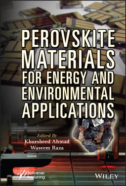
Perovskite Materials for Energy and Environmental Applications
Здесь есть возможность читать онлайн «Perovskite Materials for Energy and Environmental Applications» — ознакомительный отрывок электронной книги совершенно бесплатно, а после прочтения отрывка купить полную версию. В некоторых случаях можно слушать аудио, скачать через торрент в формате fb2 и присутствует краткое содержание. Жанр: unrecognised, на английском языке. Описание произведения, (предисловие) а так же отзывы посетителей доступны на портале библиотеки ЛибКат.
- Название:Perovskite Materials for Energy and Environmental Applications
- Автор:
- Жанр:
- Год:неизвестен
- ISBN:нет данных
- Рейтинг книги:5 / 5. Голосов: 1
-
Избранное:Добавить в избранное
- Отзывы:
-
Ваша оценка:
- 100
- 1
- 2
- 3
- 4
- 5
Perovskite Materials for Energy and Environmental Applications: краткое содержание, описание и аннотация
Предлагаем к чтению аннотацию, описание, краткое содержание или предисловие (зависит от того, что написал сам автор книги «Perovskite Materials for Energy and Environmental Applications»). Если вы не нашли необходимую информацию о книге — напишите в комментариях, мы постараемся отыскать её.
The book provides a state-of-the-art summary and discussion about the recent progress in the development and engineering of perovskite solar cells materials along with the future directions it might take.
Audience
Perovskite Materials for Energy and Environmental Applications — читать онлайн ознакомительный отрывок
Ниже представлен текст книги, разбитый по страницам. Система сохранения места последней прочитанной страницы, позволяет с удобством читать онлайн бесплатно книгу «Perovskite Materials for Energy and Environmental Applications», без необходимости каждый раз заново искать на чём Вы остановились. Поставьте закладку, и сможете в любой момент перейти на страницу, на которой закончили чтение.
Интервал:
Закладка:
Table of Contents
1 Cover
2 Title Page
3 Copyright
4 Preface
5 1 Computational Approach for Synthesis of Perovskite Solar Cells 1.1 Introduction 1.2 Preliminary Steps 1.3 Advanced Semiconductor Analysis (ASA) 1.4 Analysis of Microelectronic and Photonic Structures (AMPS) 20 1.5 Automat for Simulation of Heterostructures (AFORS-HET) 1.6 Solar Cell Capacitance Simulator (SCAPS) 1.7 Conclusion References
6 2 Fundamentals of Perovskite Solar Cells 2.1 Introduction 2.2 Structure 2.3 Working Mechanism of PSC 2.4 Device Architecture 2.5 Properties 2.6 Drawbacks and Ongoing Challenges of PSCs 2.7 Conclusion Acknowledgment References
7 3 Surface Morphological Effects on the Performance of Perovskite Solar Cells 3.1 Introduction 3.2 Morphology Control 3.3 Effect of Various Parameters on Growth of Perovskite References
8 4 Advanced Synthesis Strategies for Single Crystal Perovskite Halides 4.1 Introduction 4.2 Popular Single Crystal Growth Techniques 4.3 Other Techniques Conclusions References
9 5 Synchrotron-Based Techniques for Analysis of Perovskite Solar Cells 5.1 Introduction 5.2 Synchrotron Techniques, Their Limitations and Advantages 5.3 Synchrotron Radiation X-Ray Diffraction/Scattering (SR-XRD) 5.4 In Situ XRD 5.5 Small-Angle X-Ray Scattering 5.6 Wide-Angle X-Ray Scattering 5.7 Synchrotron Radiation-Based X-Ray Absorption Techniques 5.8 X-Ray Absorption Near Edge Structure 5.9 Extended X-Ray Absorption Fine Structure 5.10 Conclusions References
10 6 Recent Progress on Perovskite-Based Solar Cells 6.1 Introduction 6.2 Device Structure and Working Principle of PSCs 6.3 Perovskite-Based Solar Cells 6.4 Conclusion References
11 7 BiFeO 3-Based Materials For Augmented Photoactivity 7.1 Introduction 7.2 Structure, Physicochemical, and Photocatalytic Activity of BiFeO 3 7.3 Elemental Doping in BFO 7.4 BFO Semiconductor Heterojunction Construction 7.5 Separation Ability and Reproducibility 7.6 Conclusion and Perspectives 7.7 Acknowledgement References
12 8 Photocatalytic Degradation of Pollutants Using ZnTiO 3-Based Semiconductor 8.1 Introduction 8.2 Synthesis of ZnTiO 3 8.3 Fundamental Need and Basic Mechanism for Photocatalytic Degradation of Pollutants 8.4 Photocatalytic Degaradation of Pollutants Based on ZnTiO 3 8.5 Conclusion References
13 9 Types of Perovskite Materials Abbreviations 9.1 Introduction References
14 10 Effects of Various Additives to CH 3NH 3PbI 3Perovskite Solar Cells 10.1 Introduction 10.2 Crystal Structures of Perovskite Halides 10.3 Basic Configuration of Solar Cells 10.4 Cl Doping to Perovskites 10.5 Sb or As Doping to Perovskites 10.6 Highly (100)-Oriented Perovskites 10.7 Cu Doping to Perovskites 10.8 K/FA Doping to Perovskites 10.9 Morphology Control by Polysilane 10.10 High-Temperature Annealed Perovskites 10.11 Conclusion Acknowledgements References
15 Index
16 End User License Agreement
List of Illustrations
1 Chapter 1 Figure 1.1The different recombination processes in semiconductors. Figure 1.2Flowchart showing steps for calculation using ASA adapted from [3]. Figure 1.3Action panel of SCAPS. Figure 1.4Solar cell definition panel of SCAPS. Figure 1.5Layer properties panel in SCAPS. Figure 1.6Screenshot of energy bands panel window in SCAPS.
2 Chapter 2 Figure 2.1Generations of the photovoltaic cells. Figure 2.2Evolution of perovskite solar cell from reduction of size of light absorbing layer from... Figure 2.3The crystal structure of the perovskite [6]. Figure 2.4Working of the perovskite solar cell [11]. Figure 2.5Depiction of two main types of PSC [12]. Figure 2.6Schematic diagram of four types of perovskite solar cell... Figure 2.7Transitions in direct and indirect semiconductor [33]. Figure 2.8Open-circuit voltage (Voc) versus optical band gap (Eg)...
3 Chapter 3 Figure 3.1Schematic diagrams of mesoscopic heterojunction solar cell structure ... Figure 3.2Schematic of the solvent engineering process in the one-step depositi... Figure 3.3Schematic diagram of the sequential-deposition technique: Dipping in ... Figure 3.4Schematic diagram of perovskite layer from compact PbI 2(top) and por... Figure 3.5Scanning electron microscope images of PbI 2films... Figure 3.6Nucleation and growth mechanism (a) without and (b) with MAI-capped P... Figure 3.7Schematic view of the (a) HCM crystallization and (b) conventional crystallization... Figure 3.8Schematic view of conventional crystallization (top) and HCM-crystall... Figure 3.9Growth mechanism of perovskite layer on hydrophilic vs hydrophobic la... Figure 3.10Contact angles of the Porphyrin (left) and Cobalt-Porphyrin (right) ... Figure 3.11SEM images of perovskite layer deposited on (a) Porphyrin and (b) Co... Figure 3.12Schematic of the solvent vapor annealing method. Figure 3.13Schematics of the interdiffusion process and solvent vapor annealing...
4 Chapter 4 Figure 4.1(a) Diagrammatic depiction of AVC process for the growth of single crystals... Figure 4.2Diagrammatic depiction of ITC technique for the formation... Figure 4.3(a) Schematic of the experiment examination... Figure 4.4Schematic illustration of MITC technique... Figure 4.5(a) Schematic depiction of the heating process utilizing homothermal aluminum block... Figure 4.6(a) Illustrative diagram of TSSG method... Figure 4.7(a) Illustrative diagram of BSSG method along with the obtained... Figure 4.8(a) Illustrative diagram of BG technique. Reproduced from [40] with permission... Figure 4.9(a) Illustrative diagram of SE technique...
5 Chapter 5 Figure 5.1Typical lattice structure of a perovskite. Figure 5.2Schematic illustration of characterization techniques for PSCs. Figure 5.3GIXRD spectra (open cycle) around the (110) peaks for the r-perovskite... Figure 5.42D GIXRD profiles of perovskite films on... Figure 5.5 In situ XRD patterns. (a–d) Typical diffraction patterns of... Figure 5.6 In situ X-ray diffraction of perovskite annealing at... Figure 5.7Schematic illustration of synchrotron-based X-ray scattering techniqu... Figure 5.8Schematic of XAS including the pre-edge, XANES, and EXAFS regions... Figure 5.9Measured and calculated XANES spectra of C K-edge of MAPbI 3film... Figure 5.10Hypothesized process of forming a CH 3I-PbI 2defect site... Figure 5.11EXAFS spectra of CsPbBr 3(black) and CsPb 0.93Cu 0.07Br 3(red)...
6 Chapter 6 Figure 6.1Cubic geometry of perovskite oxide with the general formula of ABO 3t... Figure 6.2Schematic presentation of cubic crystal of halide perovskite with the... Figure 6.3PCE for PSCs from 2006 to 2020, data obtained from Best Research-Cell... Figure 6.4Schematic presentation of solid-state device architecture of (a) mesoscopic regular n-i-p... Figure 6.5Schematic presentation of (a) solid-state device, (b) cross-section structure... Figure 6.6(a) Diffuse reflectance spectrum, (b) Transformed Kubelka-Munk spectrum... Figure 6.7(a) XRD pattern of prepared CsPbI 2Br perovskite film at different temperatures... Figure 6.8(a) Cross-sectional SEM image of the CsPbI 2Br perovskite film with HTL and ETL on FTO... Figure 6.9(a) Crystal structure of MAPbI 3in distorted tetragonal phase... Figure 6.10(a) XRD pattern and (b) crystal of MASnI 3perovskite film showing tetragonal conformation...
Читать дальшеИнтервал:
Закладка:
Похожие книги на «Perovskite Materials for Energy and Environmental Applications»
Представляем Вашему вниманию похожие книги на «Perovskite Materials for Energy and Environmental Applications» списком для выбора. Мы отобрали схожую по названию и смыслу литературу в надежде предоставить читателям больше вариантов отыскать новые, интересные, ещё непрочитанные произведения.
Обсуждение, отзывы о книге «Perovskite Materials for Energy and Environmental Applications» и просто собственные мнения читателей. Оставьте ваши комментарии, напишите, что Вы думаете о произведении, его смысле или главных героях. Укажите что конкретно понравилось, а что нет, и почему Вы так считаете.
