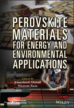
Perovskite Materials for Energy and Environmental Applications
Здесь есть возможность читать онлайн «Perovskite Materials for Energy and Environmental Applications» — ознакомительный отрывок электронной книги совершенно бесплатно, а после прочтения отрывка купить полную версию. В некоторых случаях можно слушать аудио, скачать через торрент в формате fb2 и присутствует краткое содержание. Жанр: unrecognised, на английском языке. Описание произведения, (предисловие) а так же отзывы посетителей доступны на портале библиотеки ЛибКат.
- Название:Perovskite Materials for Energy and Environmental Applications
- Автор:
- Жанр:
- Год:неизвестен
- ISBN:нет данных
- Рейтинг книги:5 / 5. Голосов: 1
-
Избранное:Добавить в избранное
- Отзывы:
-
Ваша оценка:
- 100
- 1
- 2
- 3
- 4
- 5
Perovskite Materials for Energy and Environmental Applications: краткое содержание, описание и аннотация
Предлагаем к чтению аннотацию, описание, краткое содержание или предисловие (зависит от того, что написал сам автор книги «Perovskite Materials for Energy and Environmental Applications»). Если вы не нашли необходимую информацию о книге — напишите в комментариях, мы постараемся отыскать её.
The book provides a state-of-the-art summary and discussion about the recent progress in the development and engineering of perovskite solar cells materials along with the future directions it might take.
Audience
Perovskite Materials for Energy and Environmental Applications — читать онлайн ознакомительный отрывок
Ниже представлен текст книги, разбитый по страницам. Система сохранения места последней прочитанной страницы, позволяет с удобством читать онлайн бесплатно книгу «Perovskite Materials for Energy and Environmental Applications», без необходимости каждый раз заново искать на чём Вы остановились. Поставьте закладку, и сможете в любой момент перейти на страницу, на которой закончили чтение.
Интервал:
Закладка:
7 Chapter 7 Scheme 7.1Fundamental mechanism of semiconductor-mediated photocatalysis. Figure 7.1Structure of perovskite with formula ABO 3. Figure 7.2(a) UV-Vis DRS spectra of BFO nanoparticles synthesized at 500°C showing absorption... Figure 7.3PXRD pattern of La doped BFO (reproduced from ref. no. [105]). Figure 7.4FESEM images of (a) pure BFO, (b–d) Sm (10%), and Co (5%, 10%, 15%) c... Figure 7.5XPS spectra of (a) Bi 4f, (b) Fe 2p, (c) O 1s, and (d) Gd 4d of Gd do... Figure 7.6(a) UV-Vis DRS spectra of Gd doped BFO with inset showing band gaps of pure and doped BFO... Figure 7.7(a) RhB degradation efficiency of pure and Gd doped BFO (reproduced from ref. no. [109])... Scheme 7.2Type I, type II, and type III semiconductor heterojunctions. Figure 7.8(a) Pore diameters (b) TS-SPV responses of T/P-BFO and P-BFO (reprodu... Figure 7.9(a) UV−vis DRS of BFO, CeO 2, MCeO 2, MCeO 2−BFO... Figure 7.10Mechanism for photodegradation of NFX over symmetric double Z-scheme... Figure 7.11(i) Electrochemical impedance spectra of (a) BiFeO 3and... Figure 7.12(a) Narrow S-shaped magnetic hysteresis loops of BFO...
8 Chapter 8 Figure 8.1Schematic illustration of a perovskite with the general chemical form... Figure 8.2Periodic table showing different cations and oxygen used for A and B ... Figure 8.3Synthesis of ZnTiO 3using self-assembly method [48]. Figure 8.4Mechanism for photocatalytic production of charge carrier at the surf... Figure 8.5Presentation of designing, engineering of electronic band structure and absorption... Figure 8.6(a) SEM image of hexagonal ZnTiO 3calcined at 800°C for 3 hours... Figure 8.7TEM images of (a) pristine ZnTiO 3, (b) 2% La-doped... Figure 8.8The photocatalytic degradation of RhB dye in the presence of 2% La-do... Figure 8.9(a and b) TEM and HR-TEM images of pristine ZnTiO 3, (c) TEM image of ... Figure 8.10Photocatalytic degradation of RhB dye at different calcined temperature in the presence... Figure 8.11Photocatalytic degradation of CV in the presence of (a) pristine and (b) different... Figure 8.12Photocatalytic degradation of RhB in the presence of (a) pristine and (b) different...
9 Chapter 9 Figure 9.1Pictorial representation of (a) Gustav Rose, discoverer (b) perovskit... Figure 9.2Types of perovskites materials. Figure 9.3Ideal structure of CaTiO 3(designed by materials project software). Figure 9.4Orthorhombic GdFeO 3-type structure when “t” is less than unity. Figure 9.5BaTiO 3structure (drawn by Materials Project software). Figure 9.6Showing three phases of BaTiO 3structure where O 6octahedra surrounde... Figure 9.7The cobaltite GdBaCo 2O 5.5has a perovskite related structure were Ba ... Figure 9.8Structures of selected Dion-Jacobson perovskites (CsCa 2Nb 3O 10). Figure 9.9Structures of selected Ruddlesden-Popper perovskites (K 2La 2Ti 3O 10). Figure 9.10Schematic representation of the structure of the Aurivillius compoun... Figure 9.11Crystal structure of the n = 4 Aurivillius phase BaBi 4Ti 4O 15. Figure 9.12Schematic illustration of n = 1, 2, n = 2, 3 and n = 3, 4 mixed laye...
10 Chapter 10 Figure 10.1Crystal structures of (a) cubic, (b) tetragonal, and (c) orthorhombi... Figure 10.2Crystal structures of (a) FAPbI 3, (b) CsGeI 3, and (c) CsPbBr 3. Figure 10.3(a) Fabrication process of perovskite solar cells. (b) Photograph an... Figure 10.4(a) X-ray diffraction profiles of as-deposited and annealed thin films... Figure 10.5(a) Cross-sectional transmission electron microscope image of perovskite solar cell... Figure 10.6(a) HRTEM image and (b) (100)-projected cubic CH 3NH 3PbI 3... Figure 10.7(a) Model of interfacial structure. (b) Energy level diagram of perovskite solar cell... Figure 10.8(a) Current density–voltage properties of the present devices... Figure 10.9(a) X-ray diffraction profiles of CH 3NH 3PbI 3-xCl x. (b) Enlarged prof... Figure 10.10(a) SEM image of CH 3NH 3PbI 2.88Cl 0.12device. EDS mapping images of ... Figure 10.11(a) External quantum efficiency and (b) internal quantum efficiency... Figure 10.12(a) Photoconversion efficiencies of CH 3NH 3Pb 1-xSb xI 3as a function of Sb concentration... Figure 10.13(a) X-ray diffraction profiles of CH 3NH 3Pb 1-xSb xI 3devices... Figure 10.14Optical microscope images of (a) HC(NH 2) 2PbIBr 2and (d) HC(NH 2) 2Pb0... Figure 10.15(a) Current density-voltage properties of SnBr 2or CsI addition to ... Figure 10.16(a) Current density-voltage properties of MAPbI 3(Cl) devices with a... Figure 10.17Optical microscope images of CH 3NH 3PbI 3(Cl) devices containing (a) ... Figure 10.18(a) Scanning electron microscope image of the CH 3NH 3PbI 3(Cl)... Figure 10.19EDS profiles of the present devices. Figure 10.20X-ray diffraction profiles of CH 3NH 3PbI 3(Cl)... Figure 10.21(a) Current density-voltage properties of the present devices... Figure 10.22SEM images and elemental mapping images of (a) standard, (b) + CuCl... Figure 10.23(a) Current density-voltage properties and (b) external quantum eff... Figure 10.24(a) X-ray diffraction profiles and (b) optical microscope images of... Figure 10.25Scanning electron microscope images and energy dispersive X-ray spe... Figure 10.26(a) Schematic model showing the inclusion of potassium into the perovskite... Figure 10.27(a) Structure of polysilanes. (b) Current density-voltage properties... Figure 10.28Optical microscopy images of (a) CH 3NH 3PbI 3solar cells... Figure 10.29(a), (c) Current density-voltage properties and (b), (d) EQE spectra... Figure 10.30(a) Optical microscopy images and (b) SEM images with EDS mappings... Figure 10.31X-ray diffraction profiles of (a) as-prepared MAPbI 3/(DPPS) cells... Figure 10.32Stability measurements of (a) η , (b) J SC, (c) V OC... Figure 10.33(a) Schematic illustration of microstructures, carrier dynamics and stability... Figure 10.34(a) Changes of current density-voltage properties of the...
List of Tables
1 Chapter 2 Table 2.1Types of perovskite structures. Table 2.2Band gap of different ABX 3materials [32].
2 Chapter 4 Table 4.1Various perovskite single crystals with their size and functional properties...
3 Chapter 10 Table 10.1Structure transformations of MAPbX 3. Table 10.2Crystal systems and temperatures of CsSnI 3. Table 10.3Measured structure parameters of CH 3NH 3PbI 3. Table 10.4Measured photovoltaic parameters of CH 3NH 3PbI 3-xCl xdevices. Table 10.5Measured structural parameters of the present perovskite compounds. Table 10.6Measured photovoltaic parameters of CH 3NH 3Pb 1-xSb xI 3devices. Table 10.7Measured photovoltaic parameters of the CH 3NH 3PbI 3(Cl) devices. Table 10.8Compositions and crystal orientations of the present perovskite cryst... Table 10.9Photovoltaic parameters and orientation indices of the present device... Table 10.10Estimated compositions and tolerance factors of the present perovski... Table 10.11Photovoltaic parameters of the perovskite solar cells. Table 10.12Energy gaps, lattice constants and surface coverage of the perovskit... Table 10.13Measured photovoltaic parameters and lattice constants of CH 3NH 3PbI 3... Table 10.14Measured photovoltaic parameters of MAPbI 3/(DPPS) perovskite solar cells... Table 10.15Measured compositions of the present perovskite solar cells. Table 10.16Microstructural parameters of MAPbI 3crystals...
Читать дальшеИнтервал:
Закладка:
Похожие книги на «Perovskite Materials for Energy and Environmental Applications»
Представляем Вашему вниманию похожие книги на «Perovskite Materials for Energy and Environmental Applications» списком для выбора. Мы отобрали схожую по названию и смыслу литературу в надежде предоставить читателям больше вариантов отыскать новые, интересные, ещё непрочитанные произведения.
Обсуждение, отзывы о книге «Perovskite Materials for Energy and Environmental Applications» и просто собственные мнения читателей. Оставьте ваши комментарии, напишите, что Вы думаете о произведении, его смысле или главных героях. Укажите что конкретно понравилось, а что нет, и почему Вы так считаете.


