Mohamed N. Rahaman - Materials for Biomedical Engineering
Здесь есть возможность читать онлайн «Mohamed N. Rahaman - Materials for Biomedical Engineering» — ознакомительный отрывок электронной книги совершенно бесплатно, а после прочтения отрывка купить полную версию. В некоторых случаях можно слушать аудио, скачать через торрент в формате fb2 и присутствует краткое содержание. Жанр: unrecognised, на английском языке. Описание произведения, (предисловие) а так же отзывы посетителей доступны на портале библиотеки ЛибКат.
- Название:Materials for Biomedical Engineering
- Автор:
- Жанр:
- Год:неизвестен
- ISBN:нет данных
- Рейтинг книги:4 / 5. Голосов: 1
-
Избранное:Добавить в избранное
- Отзывы:
-
Ваша оценка:
Materials for Biomedical Engineering: краткое содержание, описание и аннотация
Предлагаем к чтению аннотацию, описание, краткое содержание или предисловие (зависит от того, что написал сам автор книги «Materials for Biomedical Engineering»). Если вы не нашли необходимую информацию о книге — напишите в комментариях, мы постараемся отыскать её.
A comprehensive yet accessible introductory textbook designed for one-semester courses in biomaterials Materials for Biomedical Engineering: Fundamentals and Applications
Materials for Biomedical Engineering: Fundamentals and Applications
Materials for Biomedical Engineering — читать онлайн ознакомительный отрывок
Ниже представлен текст книги, разбитый по страницам. Система сохранения места последней прочитанной страницы, позволяет с удобством читать онлайн бесплатно книгу «Materials for Biomedical Engineering», без необходимости каждый раз заново искать на чём Вы остановились. Поставьте закладку, и сможете в любой момент перейти на страницу, на которой закончили чтение.
Интервал:
Закладка:
A perfect crystal is an idealization. Imperfections, often called defects, occur in the crystal due to packing irregularities of the atoms or the addition of other types of atoms. There are two main types of defects in crystals, classified in terms of whether they occur at one or a few atomic positions, called point defects, or over a more extended one‐dimensional line of atomic positions, called line defects or, more commonly, dislocations. These defects control the rate at which atoms can migrate through the crystal in response to a stimulus, such as mechanical stress or temperature. The attractive mechanical property of ductility in metals arises from the presence of dislocations in the crystals that make up the metal.
Unless they are formed by special and, often, expensive methods, crystalline solids are not composed of just one crystal. Instead, they are composed of a large number of small crystals, called grains, of size smaller than 1 μm to several tens of micrometers. These solids are said to be polycrystalline. The grains and, if present, amorphous phase and porosity make up the microstructure that determines the engineering properties of a material relevant to its application ( Chapter 2).
In this chapter, we will discuss the following structural features that, in addition to atomic bonding, are important for the design, properties, and applications of biomaterials:
Ways in which atoms pack to form a crystalline or an amorphous solid
Defects that are present in crystals
Microstructure of materials
3.2 Packing of Atoms in Crystals
Packing of identical atoms, such as those of a pure metal, to form crystals can be visualized in two successive steps ( Figure 3.1):
Ordered packing of atoms in two‐dimensions to form a plane or layer of atoms
Packing of these layers on top of one another to form a three‐dimensional structure.
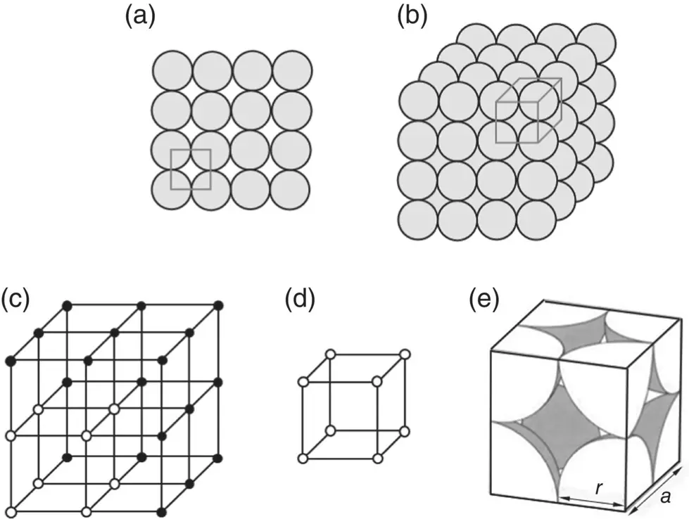
Figure 3.1 Packing of atoms to give a simple cubic structure. (a) Single “square” layer of atoms; (b) packing of layers directly on top of preceding layers; (c) part of a simple cubic lattice; (d) simple cubic unit cell; (e) illustration of atoms within a unit cell.
Metal atoms can be viewed as tiny ball bearings of the same radius but, for conciseness, to more easily show their packing arrangement in three‐dimensions, we can show their positions in space by points located at the center of each sphere. These points represent the crystal lattice, defined as the regular three‐dimensional pattern in which the atoms are arranged. As the pattern of lattice points forms an ordered array, it is not necessary to show the three‐dimensional structure of the entire crystal. Instead, a unit cell, defined as smallest unit in space which, when repeated, completely describes the crystal lattice, is used.
The structure illustrated in Figure 3.1, described as a simple cubic structure, is the simplest type of crystal structure. In this structure, the distance between two lattice points in the x , y, and z directions from a given lattice point (which we can take arbitrarily as the origin), called the unit cell length, is the same and the angle between these lines is 90°. A simple cubic structure can be created by taking the first layer of atoms, composed of this “square” arrangement of the atoms, and placing an identical layer directly on top of it. Then the third layer is placed directly on top of the second layer, and so on.
Another way of forming a cubic structure using this square layer is to take the first layer of atoms A and place the second layer of atoms B into the depressions (hollow regions) between the atoms of the first layer ( Figure 3.2). Then the third layer is placed in the depressions of the second layer, which means that it is directly above the first layer. This gives an ABAB pattern of stacking the layers. The unit cell consists of a simple cubic structure with an additional atom located at its center. The structure is referred to as body‐centered cubic, abbreviated BCC.
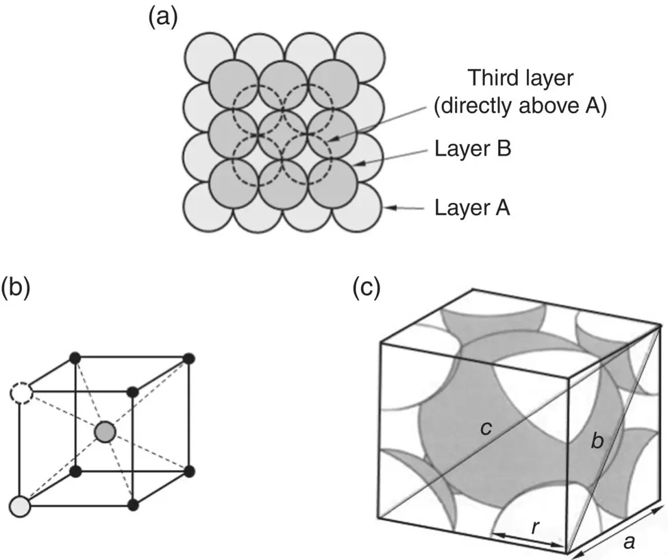
Figure 3.2 (a) Packing of “square” layers of atoms in ABAB pattern to give a body‐centered cubic (BCC) structure; (b) illustration of ABAB packing pattern in a unit cell; (c) illustration of atoms within a unit cell.
Instead of a square layer of identical atoms, we can use a “triangular” layer in which the centers of any three touching atoms from a triangle ( Figure 3.3). This triangular layer takes up the least amount of space in a plane and is called a close‐packed plane. To build a regular repeating three‐dimensional pattern, we can start with the first layer A and add a second layer by placing the atoms into the depressions of layer A. Then a third layer can be added into the depressions of the second layer, and so on. However, there are two alternative ways of stacking these additional layers. One way is to place the atoms of the second layer B into the depressions, labeled B, of the first layer. Then the third layer C can be added on top of the second layer over the depressions labeled C. By the time we get to the fourth layer, the atoms of this layer are directly above the first layer A. We call this packing sequence an ABCABC pattern and the structure formed in this way is called face‐centered cubic (FCC). The unit cell corresponds to a simple cubic structure but with additional atoms located at the center of each face.
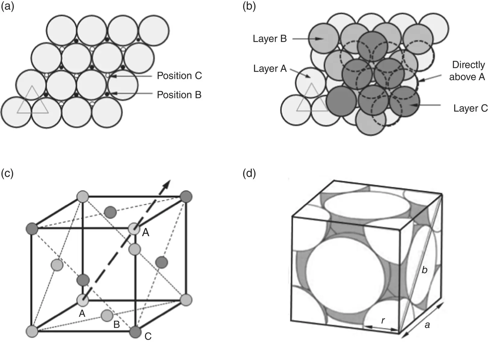
Figure 3.3 (a) Single “triangular” layer of atoms showing interstitial positions (depressions) B and C between the atoms; (b) Packing of triangular layers of atoms in ABCABC pattern to give a face‐centered cubic (FCC) structure; (c) atomic positions in a unit cell (resulting from ABCABC packing of the layers in planes perpendicular to the direction of the arrow); (d) illustration of atoms within a unit cell.
Another way to stack the triangular layer is to add the second layer B by placing the atoms into the depressions labeled B of the first layer A ( Figure 3.4). Then the atoms of the third layer are placed into the depressions of layer B which means that these atoms are directly above those of layer A. This packing sequence, called an ABAB pattern, results in a hexagonal structure referred to as close‐packed hexagonal (CPH).
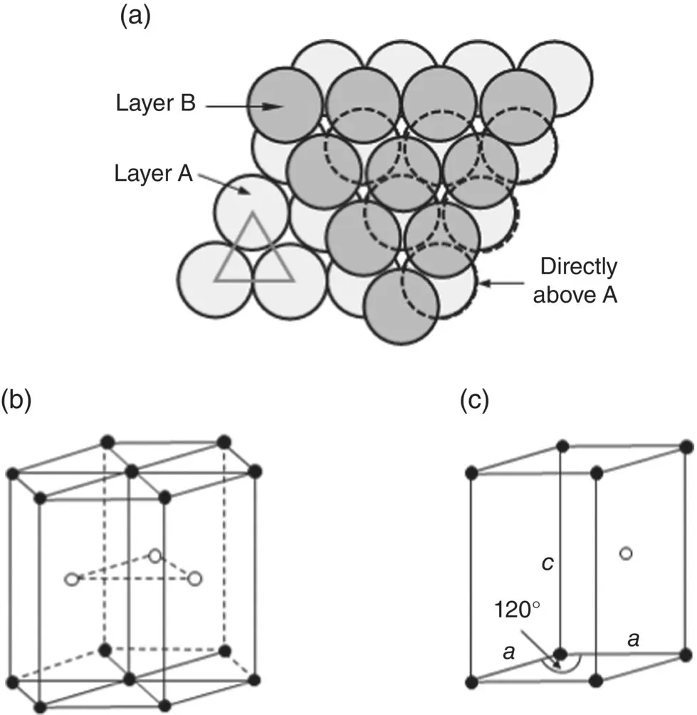
Figure 3.4 (a) Packing of triangular layers of atoms in ABAB pattern to give a close‐packed hexagonal (CPH) structure; (b) atomic positions in a hexagonal unit cell; (c) unit cell commonly used for CPH structure.
The atomic packing fraction, sometimes referred to as the packing density, of a crystal structure is defined as the fractional volume of the unit cell that is occupied by the atoms themselves, that is, the volume of the atoms divided by the volume of the unit cell. Table 3.1shows that the atomic packing fraction of the BCC structure is considerably higher than that of the simple cubic while those of the FCC and CPH structures are equal to one another and higher still.
Table 3.1 Atomic packing fractions of the simple cubic, body‐centered cubic (BCC), face‐centered cubic (FCC), and close‐packed hexagonal (CPH) structures.
Читать дальшеИнтервал:
Закладка:
Похожие книги на «Materials for Biomedical Engineering»
Представляем Вашему вниманию похожие книги на «Materials for Biomedical Engineering» списком для выбора. Мы отобрали схожую по названию и смыслу литературу в надежде предоставить читателям больше вариантов отыскать новые, интересные, ещё непрочитанные произведения.


Обсуждение, отзывы о книге «Materials for Biomedical Engineering» и просто собственные мнения читателей. Оставьте ваши комментарии, напишите, что Вы думаете о произведении, его смысле или главных героях. Укажите что конкретно понравилось, а что нет, и почему Вы так считаете.