Johan P. Reyneke - Essentials of Orthognathic Surgery
Здесь есть возможность читать онлайн «Johan P. Reyneke - Essentials of Orthognathic Surgery» — ознакомительный отрывок электронной книги совершенно бесплатно, а после прочтения отрывка купить полную версию. В некоторых случаях можно слушать аудио, скачать через торрент в формате fb2 и присутствует краткое содержание. Жанр: unrecognised, на английском языке. Описание произведения, (предисловие) а так же отзывы посетителей доступны на портале библиотеки ЛибКат.
- Название:Essentials of Orthognathic Surgery
- Автор:
- Жанр:
- Год:неизвестен
- ISBN:нет данных
- Рейтинг книги:4 / 5. Голосов: 1
-
Избранное:Добавить в избранное
- Отзывы:
-
Ваша оценка:
Essentials of Orthognathic Surgery: краткое содержание, описание и аннотация
Предлагаем к чтению аннотацию, описание, краткое содержание или предисловие (зависит от того, что написал сам автор книги «Essentials of Orthognathic Surgery»). Если вы не нашли необходимую информацию о книге — напишите в комментариях, мы постараемся отыскать её.
Essentials of Orthognathic Surgery — читать онлайн ознакомительный отрывок
Ниже представлен текст книги, разбитый по страницам. Система сохранения места последней прочитанной страницы, позволяет с удобством читать онлайн бесплатно книгу «Essentials of Orthognathic Surgery», без необходимости каждый раз заново искать на чём Вы остановились. Поставьте закладку, и сможете в любой момент перейти на страницу, на которой закончили чтение.
Интервал:
Закладка:
The occlusal, palatal, and mandibular plane angles are often used in describing an individual as “high angle” or “low angle.” High-angle individuals tend to have relatively long anterior facial heights, whereas low-angle individuals tend to have vertically short anterior facial heights.
The numeric values of tooth positions given in Table 2-13should be considered a guide to diagnosing abnormal tooth positions and to determining final dental, skeletal, and soft tissue positions. The clinician must subjectively evaluate the positioning of the teeth to determine whether they are positioned in the central trough of bone.
Table 2-13| Summary of dental relationships
| Dental relstionship | Normal value | |
| Maxillary incisor | Angle to N-A Distance to N-A Distance to A-point vertical | 22 degrees 4 mm ahead 4 to 6 mm ahead |
| Mandibular incisor | Angle to N-B Distance to N-B Distance to B-point vertical Angle to mandibular plane | 25 degrees 4 mm ahead 4 mm ahead 90 ± 7 degrees |
| Interincisal angle | Maxillary to mandibular incisor | 130 ± 6 degrees |
| Maxillary first molar | Molar to Ptv | Patient's age + 3 mm in growing individuals |
| Mandibular anterior dental height | Incisor tip to mandibular border | 44 + 2 mm (males) 40 + 2 mm (females) |
| Occlusal plane angle | Occlusal plane to S-N Occlusal plane to FH | 14 degrees 9 degrees |
Posteroanterior Cephalometric Radiographic Evaluation
In addition to lateral cephalometric radiography, individuals with facial asymmetry require posteroanterior radiographic evaluation of the facial bones. It would certainly be advantageous to obtain a CBCT image or multislice CT to facilitate virtual treatment planning (Fig 2-71). CBCT allows images to be obtained with the patient in a standing or seated position with the teeth in the preferred occlusion and the soft tissue in repose. As always, accurate image acquisition also applies here. Multislice CT scanning is performed with the patient in supine position, which will inherently falsify the 3D facial soft tissue mask of the patient, and gravity may distort the facial soft tissue in this position and interfere with the accuracy of the image. Also, careful attention should be paid to the wax-bite or registration device so the lip position or morphology will not be disturbed when taking a CT scan. (See “Virtual Surgical Planning” in chapter 3.)
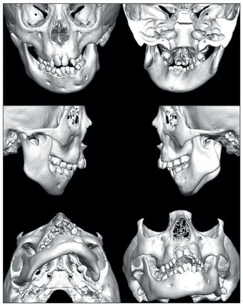
Fig 2-71The 3D CT scanned image of a patient with hemifacial microsomia. The skeletal asymmetry and agenesis of the left mandibular ramus and condyle is clearly demonstrated and allows for accurate virtual treatment planning.
Hard tissue cephalometric landmarks
Posteroanterior hard tissue landmarks, shown in Fig 2-72, include the following:
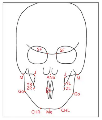
Fig 2-72Posteroanterior hard tissue cephalometric landmarks.
Spheno-frontal (SF) point: Where the smaller wing of the sphenoid bone crosses the medial orbital ridge
ANS: The center point at the base of the nose
Jugulare (J): The most superior and medial point on the zygomatic buttress
Mastoid (M): The most inferior point on the mastoid bone
A: The contact area between the maxillary incisors. Note: This is distinct from A-point.
B: The contact area between the mandibular incisors. Note: This is distinct from B-point.
Y: The most lateral point on the buccal surface area of the first maxillary molar (YL on the left and YR on the right)
Z: The most lateral point on the buccal surface area of the first mandibular molar (ZL on the left and ZR on the right)
Go: The most inferior posterior point at the angle of the mandible
Me: The most inferior point at the anterior mandibular area
CH: The most inferior lateral point on the anterior inferior border of the mandible (CHL on the left and CHR on the right)
Transverse posteroanterior cephalometric planes
Transverse posteroanterior cephalometric planes, shown in Fig 2-73, include the following:
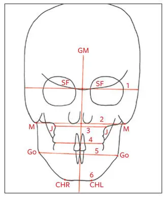
Fig 2-73Transverse posteroanterior and vertical planes. (1) Cranial base plane. (2) Mastoid plane. (3) J-plane. (4) Occlusal plane. (5) S-plane. (6) Chin plane.
Cranial base plane (C-plane): A horizontal line connecting the left and right SF points and extending laterally to the cranium
Mastoid plane (D-plane): A line connecting the left and right mastoid points
S-plane: The connecting line between the left and right Go of the mandible
J-plane: A line drawn from the left J-point to the right J-point, which is divided into two halves (IR and IL) by the geometrically constructed vertical axis (GM)
Occlusal plane: A plane formed by a line connecting the occluding points of the maxillary and mandibular buccal cusps left and right
Chin plane (CHP): A line drawn on the inferior border of the chin at maximum bone contact, through Me
Vertical posteroanterior cephalometric line
The vertical cephalometric line is called the geometrically constructed vertical axis (GM; see Fig 2-73). It is constructed by dividing the C-plane and the D-plane, connecting these two midpoints, and extending this line to the chin.
Triangular analysis
Triangles are constructed for evaluation of the symmetry of the maxilla, mandible, and chin. The maxillary triangle is constructed by connecting the midpoint of the C-plane (C-point) with points J on either side of the GM. These connecting lines are called the HR line and the HL line . The base of the triangle is divided in two halves, IR and IL, by GM (Fig 2-74a).
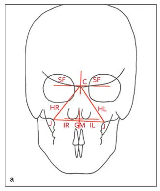
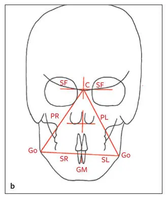
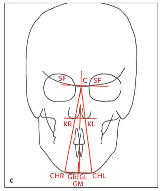
Fig 2-74 (a) Maxillary triangle. (b) Mandibular triangle. (c) Chin triangle and vertical line through B-point perpendicular to CHP.
The mandibular triangle is constructed by connecting C-point with Go bilaterally using lines PR and PL. The base of the mandibular triangle is halved into SR and SL by GM (Fig 2-74b).
The chin triangle is constructed by connecting the C-point with CHR and CHL; the long legs of the triangle are called KR and KL . A line is drawn from B-point perpendicular to CHP to evaluate the mandibular incisor midline in relation to the midline of the chin. The base of this triangle is divided into two halves, GR and GL, by GM (Fig 2-74c).
By measuring the long legs of the triangles, cants in the maxilla, mandible, and chin can be evaluated in relation to the cranial base, as well as to each other. By comparing the left and right sides of the bases of the triangles, transverse discrepancies on rotations can be assessed. Midline asymmetries of the nasal spine, Me, and dental midlines can be evaluated. Any discrepancy between the mandibular dental midline and the midpoint of the chin can be evaluated by the vertical line perpendicular to CHP (see Fig 2-74c).
Читать дальшеИнтервал:
Закладка:
Похожие книги на «Essentials of Orthognathic Surgery»
Представляем Вашему вниманию похожие книги на «Essentials of Orthognathic Surgery» списком для выбора. Мы отобрали схожую по названию и смыслу литературу в надежде предоставить читателям больше вариантов отыскать новые, интересные, ещё непрочитанные произведения.


Обсуждение, отзывы о книге «Essentials of Orthognathic Surgery» и просто собственные мнения читателей. Оставьте ваши комментарии, напишите, что Вы думаете о произведении, его смысле или главных героях. Укажите что конкретно понравилось, а что нет, и почему Вы так считаете.