Distributed Acoustic Sensing in Geophysics
Здесь есть возможность читать онлайн «Distributed Acoustic Sensing in Geophysics» — ознакомительный отрывок электронной книги совершенно бесплатно, а после прочтения отрывка купить полную версию. В некоторых случаях можно слушать аудио, скачать через торрент в формате fb2 и присутствует краткое содержание. Жанр: unrecognised, на английском языке. Описание произведения, (предисловие) а так же отзывы посетителей доступны на портале библиотеки ЛибКат.
- Название:Distributed Acoustic Sensing in Geophysics
- Автор:
- Жанр:
- Год:неизвестен
- ISBN:нет данных
- Рейтинг книги:5 / 5. Голосов: 1
-
Избранное:Добавить в избранное
- Отзывы:
-
Ваша оценка:
Distributed Acoustic Sensing in Geophysics: краткое содержание, описание и аннотация
Предлагаем к чтению аннотацию, описание, краткое содержание или предисловие (зависит от того, что написал сам автор книги «Distributed Acoustic Sensing in Geophysics»). Если вы не нашли необходимую информацию о книге — напишите в комментариях, мы постараемся отыскать её.
Distributed Acoustic Sensing in Geophysics Methods and Applications Distributed Acoustic Sensing (DAS) is a technology that records sound and vibration signals along a fiber optic cable. Its advantages of high resolution, continuous, and real-time measurements mean that DAS systems have been rapidly adopted for a range of applications, including hazard mitigation, energy industries, geohydrology, environmental monitoring, and civil engineering.
presents experiences from both industry and academia on using DAS in a range of geophysical applications. Volume highlights include: The American Geophysical Union promotes discovery in Earth and space science for the benefit of humanity. Its publications disseminate scientific knowledge and provide resources for researchers, students, and professionals.
Distributed Acoustic Sensing in Geophysics — читать онлайн ознакомительный отрывок
Ниже представлен текст книги, разбитый по страницам. Система сохранения места последней прочитанной страницы, позволяет с удобством читать онлайн бесплатно книгу «Distributed Acoustic Sensing in Geophysics», без необходимости каждый раз заново искать на чём Вы остановились. Поставьте закладку, и сможете в любой момент перейти на страницу, на которой закончили чтение.
Интервал:
Закладка:
Cable orientation is responsible not only for acoustic amplitude but also for acoustic spatial resolution, even for the same acoustic wavelength. The cable acts as an acoustic antenna where the signal varies rapidly in space if the P‐wave and cable direction coincide, but the signal remains the same over distance if the acoustic wave front is parallel to the cable. To take this effect into consideration, we need to expand the expression for acoustic wavelength K zalong the cable for Equations 1.29– 1.30as:
(1.31) 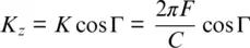
For a harmonic wave, directionality will directly affect not only the spatial resolution but also the temporal frequency. After Fourier transfer in the time domain, Equation 1.30, in the absence of aliasing, can be presented as:
(1.32) 
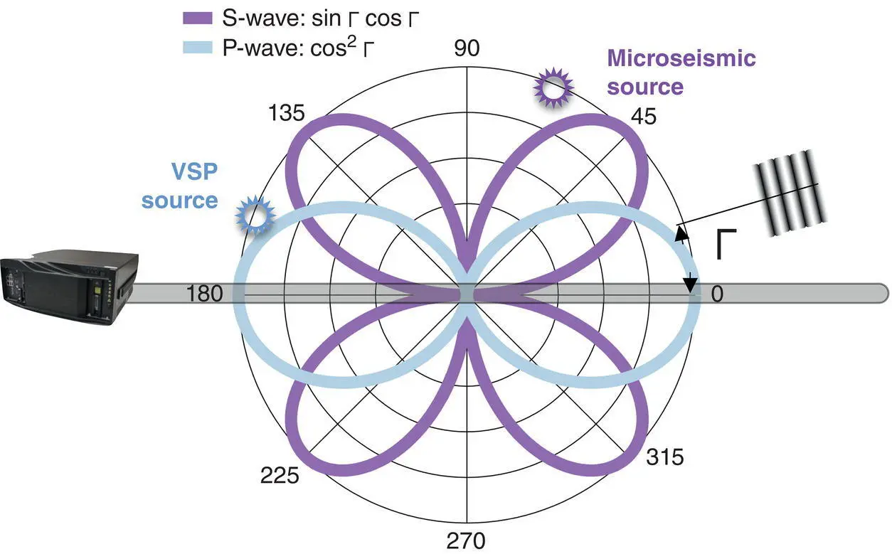
Figure 1.14 DAS with linear optical cable is more sensitive to P ‐wave in VSP configuration and to S ‐wave in microseismic events.
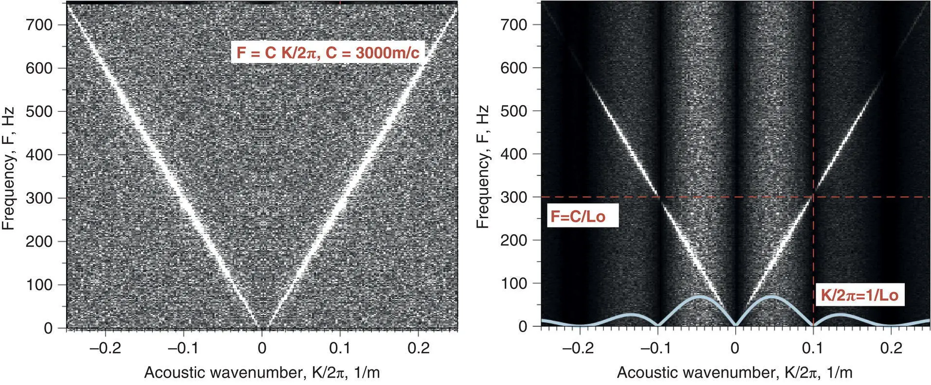
Figure 1.15 2D spectral representation on upgoing and downgoing acoustic waves: The left panel represents original signal and the right panel represents filtered signal, where the spatial filter shape is shown by a blue wavy line.
This expression ( Equation 1.32) represents spatial filtering in the 2D Fourier domain as shown in Figure 1.15for L 0= 10 m for upgoing and downgoing waves, together with white phase noise. As far as harmonic waves can be represented as single lines, the result of spatial filtering is an intensity modulation of these lines. Such modulation is equivalent to temporal frequency modulation, so we can combine Equation 1.31and Equation 1.32to get:
(1.33) 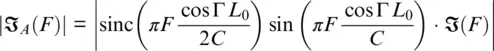
It is interesting to mention that, for uniform strain, where C → ∞, we have | ℑ A( F )| ∝ cos 2Γ as expected from Benioff (1935). The result of modeling of Equation 1.33is presented in Figure 1.16for different incident angles. An increase in angle expands the measurement frequency range but reduces low‐frequency SNR at the same time.
DAS directivity can be significantly modified through appropriate cable design, which is currently a developing area. For example, field tests have shown that the helical placement of fiber within a squeezable material can deliver omnidirectional sensitivity (Hornman et al., 2013) for P‐waves. The angular dependence will be different for S‐waves (Abbott et al., 2019), and a different helix pitch can be useful to optimize performance for different wave types (Baird, 2020). Additional complexity comes from cable construction, and the Poisson′s ratio of the cable itself can affect the angular signature (Wuestefeld & Wilks, 2019). An even more sophisticated approach can be used to measure inertial acceleration—by using a dedicated non‐isotropic cable, where a dense mass compresses the fiber along the cable (Farhadiroushan et al., 2017). Such a solution can be used for multi‐component seismic acquisition, including for analysis of microseismic events.
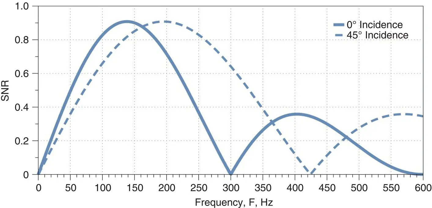
Figure 1.16 Normalized SNR curve (SNR vs. frequency) for a 3000 m/s wave speed of P ‐wave at 0° and 45° incident angles.
This analysis demonstrates that the DAS broad spectral response can potentially correspond to conventional geophones and seismometers. In the next section, we will provide some examples of how such promises can be fulfilled in field measurements.
1.2.3. DAS Field Data Examples
DAS seismic services were introduced to deliver better characterization of geophysical properties by dramatically increasing the spatial density of acquired data. DAS technology enables the collection of seismic data with a wide range of source types. For in‐well measurements, the optical fibers are embedded within ruggedized downhole cables that can be conveyed loosely in the well (wireline), or clamped to tubing and/or cemented with the completion, thereby offering a permanent sensor array ( Figure 1.17). The usual assumption is that the stretching of the optical cable coincides with the deformation of the ground in the acoustic wave. In turn, the length of the optical fiber tracks the length of the optical cable due to internal friction. When the cable is attached to a pipe, the pipe deformation coincides with the ground deformation. If the cable is poorly connected to the pipe between the clamps, then lines on the VSP has a staircase‐like shape. The period of the steps equals the distance between the clamps, which is about 10 m. Fortunately, this value does not significantly exceed the DAS resolution and practically does not degrade the quality of the VSP pattern.
A typical VSP seismic shot response for permanently installed fiber optic cable behind the casing is shown in Figure 1.18for both the raw acoustic data and with the denoising algorithm applied.
An important practical question is the ability of the DAS to perform measurements on both single‐mode (SM) and multi‐mode (MM) optical fiber, since MM fiber has been deployed in many legacy installations. It was found experimentally that seismic data can be recorded equally well on both SM and MM fiber. This is achieved as the fundamental mode LP 01size diameter in MM fiber (14 μm) is nearly matched to SM fiber (10 μm), and, therefore, the DAS performance using MM fiber is similar to that from SM fiber. Strictly speaking, the SNR in MM fiber can be slightly worse at the near end of the fiber because of the optical coupling loss, and slightly better at the far end of the fiber because its larger core diameter allows higher optical power transmission along the fiber. Similar performance for SM and MM fiber was observed in field experiments (see Figure 1.19) when two fibers were placed side by side in an optical cable. These results show the feasibility of retrofitting DAS to existing MM fiber installations and so utilizing distributed temperature sensing infrastructure to perform the full scope of DAS services, which include not only seismic measurements but also well diagnostics and flow monitoring (Finfer et al., 2014).
For VSP applications in vertical wells, the direction of the well and fiber optic cable coincides for near‐offsets with the seismic wave propagation, and so DAS is mostly sensitive to P‐waves. This effect was tested by comparison with transverse and vertical geophones (see Figure 1.20). The geophone with transverse orientation (left panel) has not detected the P‐wave, whereas the geophone with vertical orientation (central panel) has. The DAS (right panel) also has detected the P‐wave as expected. It is worth noting that the case for far offsets is more complicated (Mateeva et al., 2014).
Читать дальшеИнтервал:
Закладка:
Похожие книги на «Distributed Acoustic Sensing in Geophysics»
Представляем Вашему вниманию похожие книги на «Distributed Acoustic Sensing in Geophysics» списком для выбора. Мы отобрали схожую по названию и смыслу литературу в надежде предоставить читателям больше вариантов отыскать новые, интересные, ещё непрочитанные произведения.


Обсуждение, отзывы о книге «Distributed Acoustic Sensing in Geophysics» и просто собственные мнения читателей. Оставьте ваши комментарии, напишите, что Вы думаете о произведении, его смысле или главных героях. Укажите что конкретно понравилось, а что нет, и почему Вы так считаете.