Distributed Acoustic Sensing in Geophysics
Здесь есть возможность читать онлайн «Distributed Acoustic Sensing in Geophysics» — ознакомительный отрывок электронной книги совершенно бесплатно, а после прочтения отрывка купить полную версию. В некоторых случаях можно слушать аудио, скачать через торрент в формате fb2 и присутствует краткое содержание. Жанр: unrecognised, на английском языке. Описание произведения, (предисловие) а так же отзывы посетителей доступны на портале библиотеки ЛибКат.
- Название:Distributed Acoustic Sensing in Geophysics
- Автор:
- Жанр:
- Год:неизвестен
- ISBN:нет данных
- Рейтинг книги:5 / 5. Голосов: 1
-
Избранное:Добавить в избранное
- Отзывы:
-
Ваша оценка:
Distributed Acoustic Sensing in Geophysics: краткое содержание, описание и аннотация
Предлагаем к чтению аннотацию, описание, краткое содержание или предисловие (зависит от того, что написал сам автор книги «Distributed Acoustic Sensing in Geophysics»). Если вы не нашли необходимую информацию о книге — напишите в комментариях, мы постараемся отыскать её.
Distributed Acoustic Sensing in Geophysics Methods and Applications Distributed Acoustic Sensing (DAS) is a technology that records sound and vibration signals along a fiber optic cable. Its advantages of high resolution, continuous, and real-time measurements mean that DAS systems have been rapidly adopted for a range of applications, including hazard mitigation, energy industries, geohydrology, environmental monitoring, and civil engineering.
presents experiences from both industry and academia on using DAS in a range of geophysical applications. Volume highlights include: The American Geophysical Union promotes discovery in Earth and space science for the benefit of humanity. Its publications disseminate scientific knowledge and provide resources for researchers, students, and professionals.
Distributed Acoustic Sensing in Geophysics — читать онлайн ознакомительный отрывок
Ниже представлен текст книги, разбитый по страницам. Система сохранения места последней прочитанной страницы, позволяет с удобством читать онлайн бесплатно книгу «Distributed Acoustic Sensing in Geophysics», без необходимости каждый раз заново искать на чём Вы остановились. Поставьте закладку, и сможете в любой момент перейти на страницу, на которой закончили чтение.
Интервал:
Закладка:
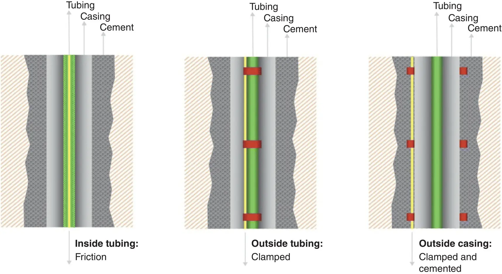
Figure 1.17 Sensing optical fiber cable deployments.
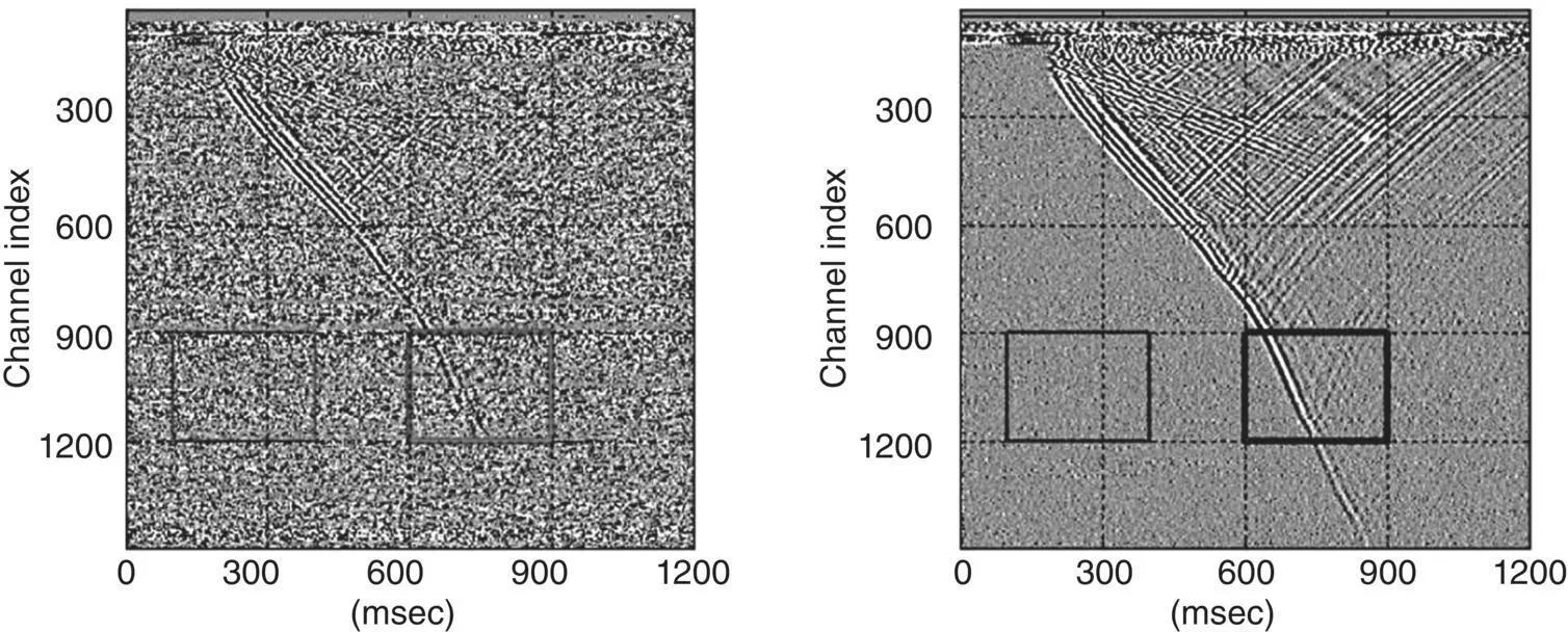
Figure 1.18 The left‐hand panel shows a single shot of raw acoustic data; the right‐hand panel shows the same shot with denoising applied from Miller et al. (2016).
A comparison of DAS data (converted from strain rate to particle velocity) to co‐located geophones indicates that the DAS data is consistent with geophone response. As a result, a 3D VSP image can be collected from multiple dynamite shots in a similar manner as for conventional geophones (Miller et al., 2016). The DAS records the seismic signal at every point along the optical fiber with each source activation, leading to much greater receiver coverage than is achievable with conventional borehole seismic methods. A typical result of DAS 3D VSP is presented in Figure 1.21.
Fine spatial resolution, in combination with good sensitivity and dynamic range, gives DAS a significant advantage for hydraulic fracture monitoring and the detection of microseismic events, particularly where a geophone chain cannot be readily positioned, such as in a treatment well. Figure 1.22shows a waterfall plot (depth vs time), recording strong acoustic signals, corresponding to fluid placement across individual clusters, while, at the same time, detecting small microseismic events.
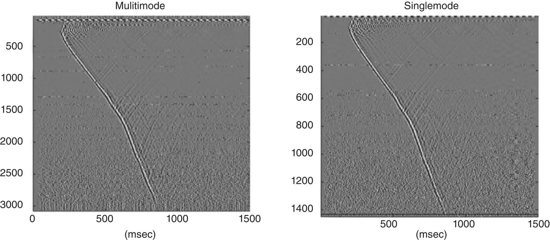
Figure 1.19 Comparison of DAS performance with SM and MM optical fiber.

Figure 1.20 Directionality of DAS response: The left and central panels represent geophones with transverse and vertical orientation, and the right panel represents the DAS signal for VSP.
Optical fiber can also be used for offset well monitoring, as indicated in Figure 1.23. Here, the optical fiber cable, cemented behind the casing in the originally treated well, is used to monitor microseismic events and strain while an offset well is being treated. The shape and arrival time of P‐ and S‐waves can be used for microseismic event picking and localization. The data can be used for optimizing the well spacing, cluster spacing, and stimulation parameters.
In summary, DAS is a new, versatile technology that can be deployed in many different configurations along boreholes where geophones cannot readily be deployed. The frequency response of DAS is comparable with geophones and can offer the benefits of wide aperture monitoring along the entire borehole with broad frequency response. Improvements in optical fibers and cable designs offer new possibilities for the DAS monitoring of geophysical properties.
1.3. DAS WITH PRECISION ENGINEERED FIBER
In this chapter, we consider how the scattering properties of conventional fiber can be engineered to deliver better DAS performance ( Figure 1.24). We will show how an SNR improvement can be achieved, along with a wider dynamic range, using engineered fiber with precisely uniform scattering centers. This approach differs from a simple increase in irregular backscattering intensity (Westbrook et al., 2017). We also consider the trade‐offs between spatial resolution, signal‐to‐noise performance and frequency response, and present data acquired from several different seismic and microseismic surveys.
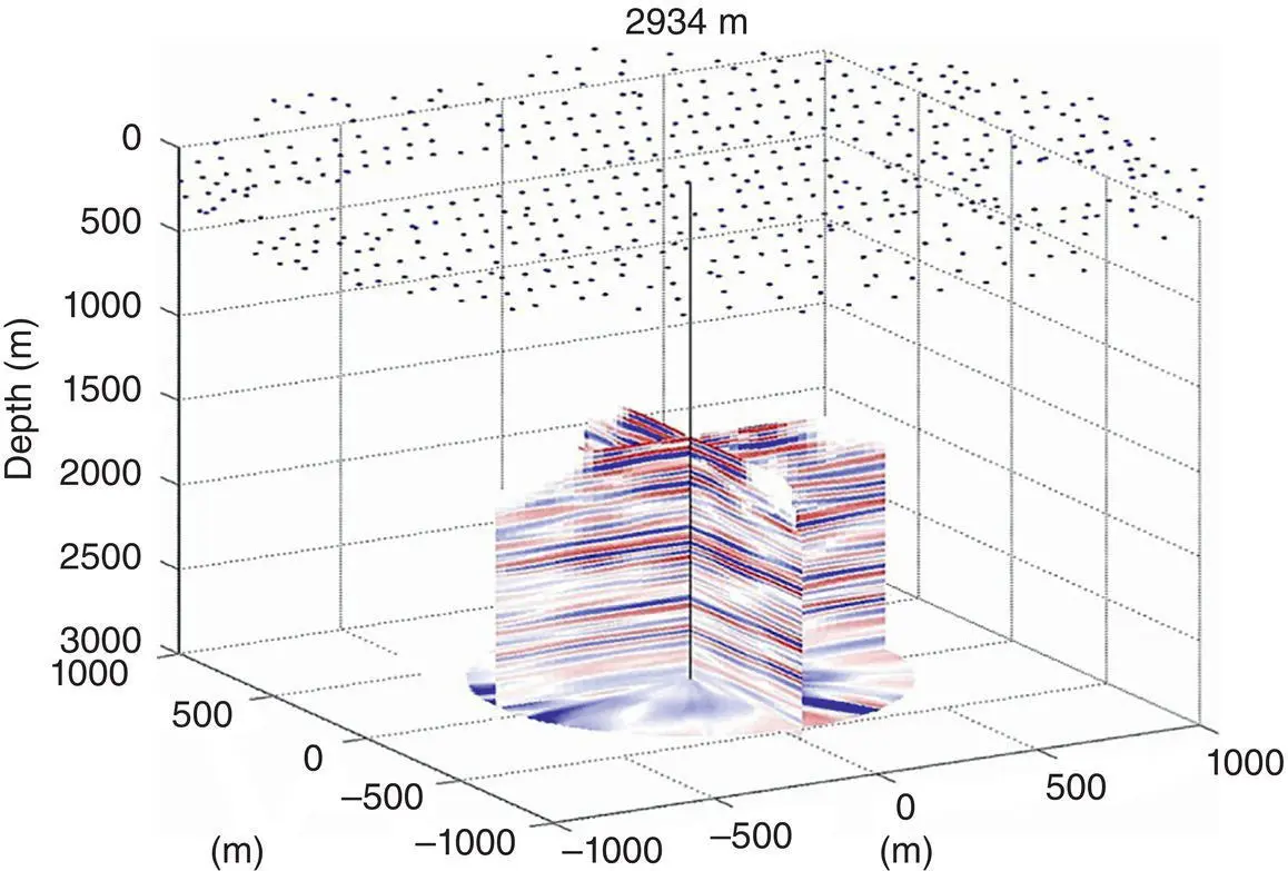
Figure 1.21 3D VSP: Two intersecting images processed from DAS seismic data acquired with the dynamite shot positions indicated from Miller et al. (2016).
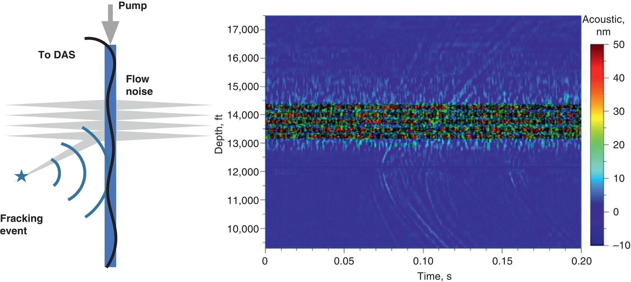
Figure 1.22 DAS hydraulic fracture monitoring in the treatment well with a fine spatial resolution and wide dynamic range for simultaneous cluster fluid allocation and microseismic monitoring.
DAS performance is largely governed by how much light can be usefully collected from the optical fiber. In general, we require low‐loss fiber for long range sensing, but higher scattering fiber to generate more light. These two apparently contradictory requirements can be balanced by engineering bright scatter centers in the fiber, without introducing significant excess loss for the forward propagating light. This can be achieved, for example, by using fiber Bragg grating technology.
For long fiber lengths, 100 times more light than Rayleigh level can be safely used (Farhadiroushan et al., 2021). That gives 20 dB reduction of acoustic noise caused by quantum shot noise at frequencies of around 1 kHz. This improvement can be even more at low frequencies as pink noise is suppressed by the regular structure of scattering. So, noise reduction can be more than 30 dB at around 1 Hz. This prediction was successfully confirmed in field surveys and are presented at the end of the chapter.
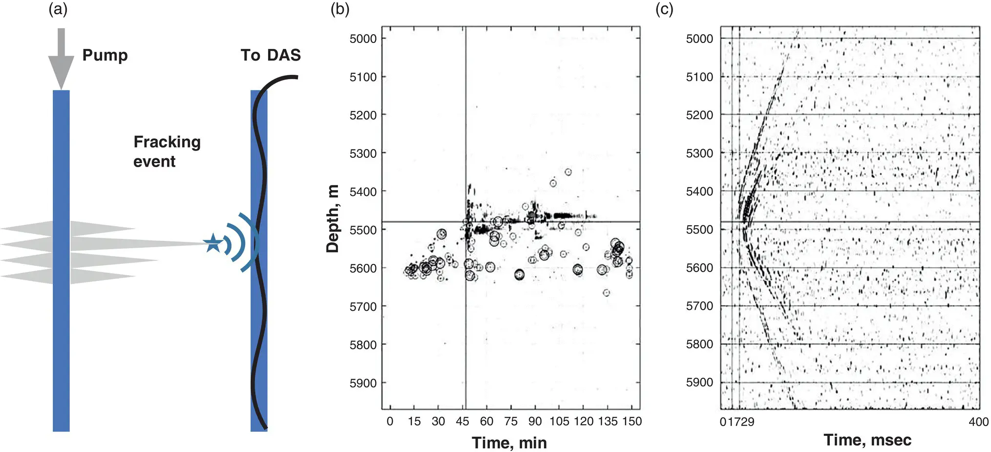
Figure 1.23 DAS hydraulic fracture monitoring in the offset (a) with a fine spatial resolution for microseismic monitoring (c), and localizing of microseismic events in time and space (b).
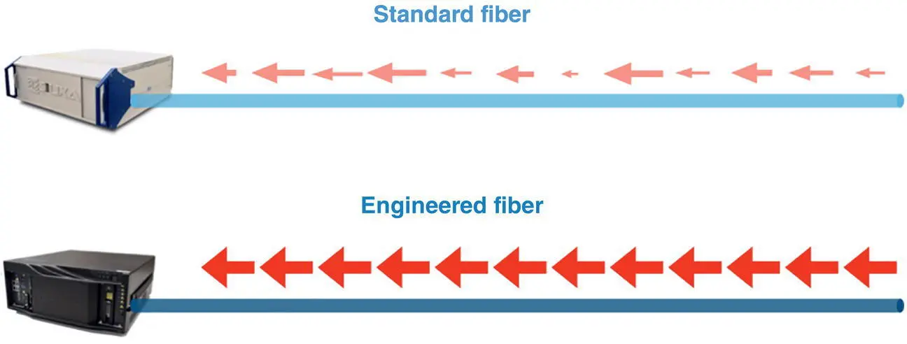
Figure 1.24 DAS with standard fiber and engineered fiber with precision bright scatter center zones.
1.3.1. Precision engineered fiber concept
We will start our consideration from Equation 1.6in Section 1.1(titled ‘Distributed Acoustic Sensor (DAS) Principles and Measurements’), which represents the scattered E ( z , t ) field as a convolution of input optical field with scattering coefficient r ( z ), for a gauge length L 0.
(1.34) 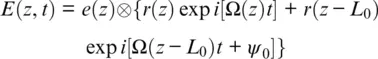
where e ( z ) is a coherent optical pulse and Ω( z ) ∝ v ( z ) is the Doppler shifted angular frequency, which is proportional to the local acoustic speed—see Figure 1.25.
The scattering coefficient for engineered fiber can be represented by a spatially periodic function (Farhadiroushan et al., 2021), meaning a reflection coefficient r ( z ) can be represented by a set of defined scatter center zones separated by sampling distance L S.
(1.35) 
Интервал:
Закладка:
Похожие книги на «Distributed Acoustic Sensing in Geophysics»
Представляем Вашему вниманию похожие книги на «Distributed Acoustic Sensing in Geophysics» списком для выбора. Мы отобрали схожую по названию и смыслу литературу в надежде предоставить читателям больше вариантов отыскать новые, интересные, ещё непрочитанные произведения.


Обсуждение, отзывы о книге «Distributed Acoustic Sensing in Geophysics» и просто собственные мнения читателей. Оставьте ваши комментарии, напишите, что Вы думаете о произведении, его смысле или главных героях. Укажите что конкретно понравилось, а что нет, и почему Вы так считаете.