Iam-Choon Khoo - Liquid Crystals
Здесь есть возможность читать онлайн «Iam-Choon Khoo - Liquid Crystals» — ознакомительный отрывок электронной книги совершенно бесплатно, а после прочтения отрывка купить полную версию. В некоторых случаях можно слушать аудио, скачать через торрент в формате fb2 и присутствует краткое содержание. Жанр: unrecognised, на английском языке. Описание произведения, (предисловие) а так же отзывы посетителей доступны на портале библиотеки ЛибКат.
- Название:Liquid Crystals
- Автор:
- Жанр:
- Год:неизвестен
- ISBN:нет данных
- Рейтинг книги:4 / 5. Голосов: 1
-
Избранное:Добавить в избранное
- Отзывы:
-
Ваша оценка:
Liquid Crystals: краткое содержание, описание и аннотация
Предлагаем к чтению аннотацию, описание, краткое содержание или предисловие (зависит от того, что написал сам автор книги «Liquid Crystals»). Если вы не нашли необходимую информацию о книге — напишите в комментариях, мы постараемся отыскать её.
Liquid Crystals,
Liquid Crystals
Liquid Crystals
Liquid Crystals — читать онлайн ознакомительный отрывок
Ниже представлен текст книги, разбитый по страницам. Система сохранения места последней прочитанной страницы, позволяет с удобством читать онлайн бесплатно книгу «Liquid Crystals», без необходимости каждый раз заново искать на чём Вы остановились. Поставьте закладку, и сможете в любой момент перейти на страницу, на которой закончили чтение.
Интервал:
Закладка:
The first principle of continuum theory, therefore, neglects the details of the molecular structures. Liquid crystal molecules are viewed as rigid rods; their entire collective behavior may be described in terms of the director axis  , a vector field. In this picture, the spatial variation of the order parameter is described by
(3.2) 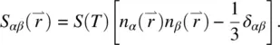
In other words, in a spatially “distorted” nematic crystal, the local optical properties are still those pertaining to a uniaxial crystal and remain unchanged; it is only the orientation (direction) of  that varies spatially.
For nematics, the states corresponding to  and –
and –  are indistinguishable. In other words, even if the individual molecules possess permanent dipoles (actually, most liquid crystal molecules do), the molecules are collectively arranged in such a way that the net dipole moment is vanishingly small; that is, there are just as many dipoles up as there are dipoles down in the collection of molecules represented by
  .
.
3.2.2. Elastic Constants, Free Energies, and Molecular Fields
Upon application of an external perturbation field, a nematic liquid crystal will undergo deformation just as any solid. There is, however, an important difference. A good example is shown in Figure 3.1a, which depicts a “solid” subjected to torsion, with one end fixed. In ordinary solids, this would create very large stress, arising from the fact that the molecules are translationally displaced by the torsional stress. On the other hand, such twist deformations in liquid crystals, owing to the fluidity of the molecules, simply involve a rotation of the molecules in the direction of the torque; there is no translational displacement of the center of gravity of the molecules, and thus, the elastic energy involved is quite small. Similarly, other types of deformations such as splay and bend deformations, as shown in Figure 3.1b and c, respectively, involving mainly changes in the director axis  , will incur much less elastic energy change than the corresponding ones in ordinary solids. It is evident from Figure 3.1a–c that the splay and bend deformations necessarily involve flow of the liquid crystal, whereas the twist deformation does not. We will return to these couplings between flow and director axis deformation in Section 3.5.
Twist, splay, and bend are the three principal distinct director axis deformations in nematic liquid crystals. Since they correspond to spatial changes in  , the basic parameters involved in the deformation energies are various spatial derivatives (i.e. curvatures of
  , such as
  and
and  , etc.). Following the theoretical formalism first developed by Frank [1], the free‐energy densities (in units of energy per volume) associated with these deformations are given by
(3.3) 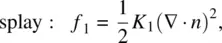
(3.4) 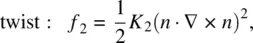
(3.5) 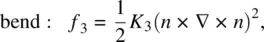
where K 1, K 2, and K 3are the respective Frank elastic constants.
In general, the three elastic constants are different in magnitude. Typically, they are on the order of 10 −6dyne in centimeter‐gram‐second (cgs) units (or 10 −11N in meter‐kilogram‐second [mks] units). For p ‐methoxybenzylidene‐ p′ ‐butylaniline (MBBA), K 1, K 2, and K 3are, respectively, 5.8 × 10 −7, 3.4 × 10 −7, and 7 × 10 −7dyne. For almost all nematics K 3is the largest, as a result of the rigid‐rod shape of the molecules.
In general, more than one form of deformation will be induced by an applied external field. If all three forms of deformation are created, the total distortion free‐energy density is given by
(3.6) 
This expression, and the resulting equations of motion and analysis, can be greatly simplified if one makes a frequently used assumption, namely, the one‐constant approximation ( K 1= K 2= K 3= K ). In this case, Eq. (3.6)becomes
(3.7) 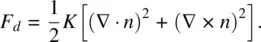
Equation (3.6)or its simplified version, Eq. (3.7), describes the deformation of the director axis vector field  in the bulk of the nematic liquid crystal. A complete description should include the surface interaction energy at the nematic liquid crystal cell boundaries. To account for this, the total energy density of the system should be
(3.8) 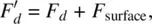
where the surface energy term is dependent on the surface treatment. In other words, the equilibrium configuration of the nematic liquid crystal is obtained by a minimization of the total free energy of the system, 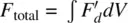 . If external fields (electric, magnetic, or optical) are applied, the corresponding free‐energy terms (see the following sections) will be added to the total free‐energy expression.
Under the so‐called hard‐boundary condition, in which the liquid crystal molecules are strongly anchored to the boundary and do not respond to the applied perturbation fields (see Figure 3.2), the surface energy may thus be regarded as a constant; the surface interactions therefore do not enter into the dynamical equations describing the field‐induced effects in nematic liquid crystals.
Читать дальшеИнтервал:
Закладка:
Похожие книги на «Liquid Crystals»
Представляем Вашему вниманию похожие книги на «Liquid Crystals» списком для выбора. Мы отобрали схожую по названию и смыслу литературу в надежде предоставить читателям больше вариантов отыскать новые, интересные, ещё непрочитанные произведения.


Обсуждение, отзывы о книге «Liquid Crystals» и просто собственные мнения читателей. Оставьте ваши комментарии, напишите, что Вы думаете о произведении, его смысле или главных героях. Укажите что конкретно понравилось, а что нет, и почему Вы так считаете.