Ralph Grabowski - AutoCAD For Dummies
Здесь есть возможность читать онлайн «Ralph Grabowski - AutoCAD For Dummies» — ознакомительный отрывок электронной книги совершенно бесплатно, а после прочтения отрывка купить полную версию. В некоторых случаях можно слушать аудио, скачать через торрент в формате fb2 и присутствует краткое содержание. Жанр: unrecognised, на английском языке. Описание произведения, (предисловие) а так же отзывы посетителей доступны на портале библиотеки ЛибКат.

- Название:AutoCAD For Dummies
- Автор:
- Жанр:
- Год:неизвестен
- ISBN:нет данных
- Рейтинг книги:5 / 5. Голосов: 1
-
Избранное:Добавить в избранное
- Отзывы:
-
Ваша оценка:
AutoCAD For Dummies: краткое содержание, описание и аннотация
Предлагаем к чтению аннотацию, описание, краткое содержание или предисловие (зависит от того, что написал сам автор книги «AutoCAD For Dummies»). Если вы не нашли необходимую информацию о книге — напишите в комментариях, мы постараемся отыскать её.
AutoCAD For Dummies
AutoCAD For Dummies
AutoCAD For Dummies — читать онлайн ознакомительный отрывок
Ниже представлен текст книги, разбитый по страницам. Система сохранения места последней прочитанной страницы, позволяет с удобством читать онлайн бесплатно книгу «AutoCAD For Dummies», без необходимости каждый раз заново искать на чём Вы остановились. Поставьте закладку, и сможете в любой момент перейти на страницу, на которой закончили чтение.
Интервал:
Закладка:
 The steps in this chapter, unlike the steps in most chapters in this book, form a sequence. You must complete the steps in order. Figuring out how to use AutoCAD is a little like figuring out how to drive, in which parallel parking comes before Indy car racing, except that with AutoCAD you’re free to stop in the middle of the street and take a break. If things get away from you, press Esc two or three times to terminate any command that’s in progress, and type the letter Uand then press the Enter key to undo the last thing you did. Incidentally, U and UNDO are two similar commands and between them are probably the most-often-used commands in AutoCAD.
 If you find that selecting and editing objects work differently from the way I describe in this chapter, you have (or someone else has) probably changed the configuration settings on the Selection tab in the Options dialog box. Chapter 24describes these settings and how to restore the AutoCAD defaults.
A Simple Setup
In this chapter, I walk you through the steps to create, edit, view, and plot a new drawing. See Figure 3-1 to get an idea of what the finished product looks like. I use Imperial units in this chapter (you know — inches and feet, for example). I describe how to set imperial units versus metric units in Chapter 4.
In the following exercise, you use several of the status bar buttons at the bottom of the screen. I don’t like the icons that AutoCAD displays, and I grew bored from hovering the mouse cursor over each button until the tooltip appeared. Earlier versions of AutoCAD allowed us to switch from icons to text mode, wherein each button had a text label instead of an icon. Unfortunately, AutoCAD no longer supports this feature, so I have to refer to each button by its tooltip description along with the relevant icon in the margin. The good news is that you can toggle ten of those settings by using the F keys (such as F3), which I reference in the text in parentheses, as in (F3).
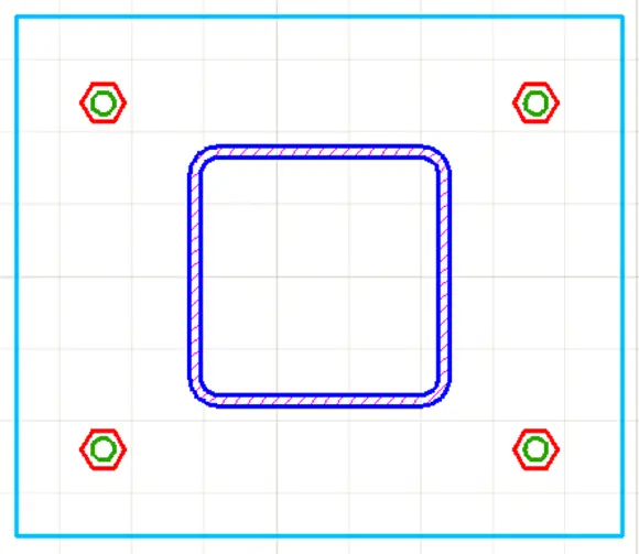
FIGURE 3-1:How base is my plate.
A gray icon indicates that the button’s function is Off, while a light blue icon indicates On. (Your screen might show icons against a dark gray background, but I used a white background for a clearer image on the printed page.)
You can find the files I use in this sequence of steps at this book’s companion website: Go to www.dummies.com/go/autocadfd19 and download afd03.zip. The Zip file contains imperial and metric versions of the base plate exercise at various stages, and the Read Me file on the Downloads tab describes the files in details.
Pay attention to feedback from AutoCAD. Glance at the messages the program sends you after each step via the command line at the bottom of the screen or the Dynamic Input tooltip near the cursor so that you become familiar with the names of commands and their options. If you want to see messages next to the cursor as you use the program, click the Dynamic Input (F12) button on the status bar so that its icon is light blue rather than gray.
In this first set of steps, you create a new drawing from a template, change a few settings to establish a 1:10 scale (that is, 1 inch on the drawing is equivalent to 10 inches on the real object), and save the drawing:
1 Start AutoCAD.As indicated in Chapter 1, the startup procedure can vary depending on your version of Windows and how it is set up.
2 Start a new drawing that uses AutoCAD’s Imperial template. Click the down arrow next to the New button on the Start tab. Don’t click the big New button itself or the New button on the Quick Access toolbar. You must use the down arrow. I explain why in Chapter 4— humor me for now. Have I lied to you recently?A list of drawing templates (DWT files) appears. Templates in AutoCAD are similar to templates in Microsoft Word and other programs. Chapter 4describes how and why to create and use custom drawing templates. If the acad.dwt file name is missing from the list, select Browse Templates. In the Select Template dialog box that appears, select acad.dwt, as shown in Figure 3-2 . (In AutoCAD LT, select acadlt.dwt.) AutoCAD creates a new, blank drawing that uses the settings in acad.dwt. The acad.dwt template (acadlt.dwt in AutoCAD LT) is AutoCAD’s default, plain-Jane (or should that be plain-Pat to be gender-neutral?) template for creating drawings that use imperial units (units expressed in inches or feet or both). Chapter 4contains additional information about these and other templates. FIGURE 3-2:Starting a new drawing from a template.
3 Check your workspace. The workspaces in AutoCAD look similar. To make sure that you’re using the same workspace as I am in this chapter (and in most of this book), click the gear icon, near the right end of the status bar (and shown in the margin). If the check mark in the drop-down list isn’t beside Drafting & Annotation, click Drafting & Annotation .
4 Set up the initial working environment.Make the following settings: Click all the buttons on the left half of the status bar as necessary until they look gray, except Dynamic Input (F12) and Ortho (F8), which should be blue. Turn the background grid (F7) on or off, your choice. Most beginners seem to like it turned on, and most experienced users turn it off.Some of the other settings can make point selection difficult. Start with them all turned off, and then toggle them on and off as needed. I tell you which ones to use in the remaining steps.
5 Set the drawing limits that define the working area.Type LIMITS and press Enter.(I explain drawing limits in more detail in Chapter 4.) For now, ignore the Dynamic Input tooltip next to the cursor, and look at the command line. AutoCAD echoes the command name and replies to it. Set the limits of the drawing area by responding to the prompts : Specify lower left corner or [ON/OFF] <0.0000,0.0000>: Press EnterSpecify upper right corner <12.0000,9.0000>: 100,50 Don’t add a space before or after the comma of a coordinate value. It’s the final frontier. If you press the spacebar before you enter the entire coordinate value, AutoCAD will process only the text you've typed.
6 Display the defined working area. Start the Zoom command. The Zoom command is hidden away on the Ribbon, so it is usually far faster and easier to simply type Z and press Enter.ZOOM Specify corner of window, enter a scale factor (nX or nXP), or [All/Center/Dynamic/Extents/Previous/Scale/Window/Object] :… Type Aand press Enter. AutoCAD zooms so that the screen shows the limits (that is, All ) of your drawing. I use a special font to show you what AutoCAD is saying. You either type the characters in bold and press Enter, or just press Enter (such as in Step 4a) to accept AutoCAD’s default option or recent value. For simplicity, rather than show AutoCAD’s complete response, I often show only what’s necessary for you to understand what’s going on.
7 Establish the snap and grid drafting settings. Right-click the Display Drawing Grid button near the left end of the status bar and then choose Grid Settings. The Snap and Grid tab in the Drafting Settings dialog box appears, as shown in Figure 3-3. Note that AutoCAD LT lacks some options here that are present in the full version of AutoCAD. Change the values in the Drafting Settings dialog box to match those in Figure 3-3 , and click OK when you’re finished: Snap On: When selected, constrains the cursor to moving in an invisible grid of equally spaced points (0.5 units apart, in this case). Grid On: When selected, displays a visible grid of little dots or grid lines on the screen (5 units apart, in this case), which you can use as reference points. The grid doesn’t appear on printed drawings. Snap X Spacing: 0.5 Snap Y Spacing: 0.5 Grid X Spacing: 0.5 Grid Y Spacing: 0.5 Major line every : 5You see a network of grid lines, 0.5 units apart, with brighter lines every 5 units, in the drawing area. If you move the mouse pointer around and watch the coordinate display area at the left side of the status bar, you notice that the values still change in tiny increments, just as they did before. I have more information on snap mode and grid display in Chapter 4. FIGURE 3-3:Snap and Grid settings.
Читать дальшеИнтервал:
Закладка:
Похожие книги на «AutoCAD For Dummies»
Представляем Вашему вниманию похожие книги на «AutoCAD For Dummies» списком для выбора. Мы отобрали схожую по названию и смыслу литературу в надежде предоставить читателям больше вариантов отыскать новые, интересные, ещё непрочитанные произведения.


Обсуждение, отзывы о книге «AutoCAD For Dummies» и просто собственные мнения читателей. Оставьте ваши комментарии, напишите, что Вы думаете о произведении, его смысле или главных героях. Укажите что конкретно понравилось, а что нет, и почему Вы так считаете.